GBC AdvancedPunch Pro
08/20/2015
Repairs/Adjustments
4-69
REP 2.25.5 Double Punch (Large) Backage Sensor Board Assembly
(S18, S19) and Double Punch (X-Large) Backage Sensor Board
Assembly (S20, S21) Replacement
PARTS LIST ON PL 4.1
Use this procedure to remove and install the Backage Sensor Board
(S18, S19) or the Backage Sensor Board (S20, S21).
WARNING
Do not perform repair activities with the power on or electrical power
supplied to the machine. Some machine components contain
dangerous electrical voltages that can result in electrical shock and
possible serious injury. See Section 0, page vi for other languages.
1. Switch power OFF to entire printing system.
2. Disconnect the Power Cord.
3. Do REP 1.6 to remove the Rear Cover.
4. Do REP 3.1
remove the Punch Module
.
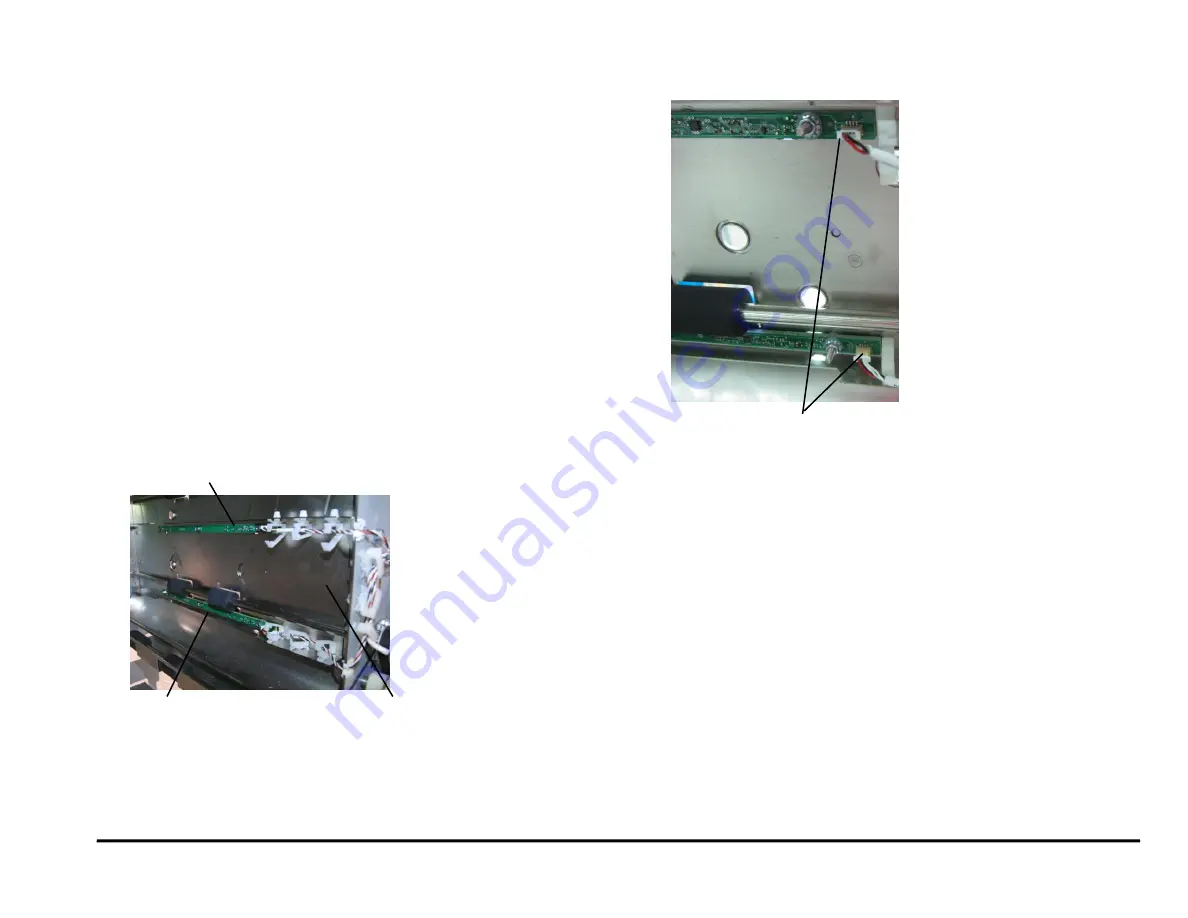
5. Locate the Drive Entrance Panel
The upper board is the Backage Sensor Board
(S20, S21).
The lower board is the Backage Sensor Board
(S18, S19).
6. Disconnect the Sensor Board Connectors (2).
7. Remove the Nuts (3) and Washers (3).
8. Remove the old Backage Sensor Board.
9. Place the new Punch Sensor Board in position.
10. Place the Washers (3) in position and tighten the Nuts (3).
11. Connect the Sensor Board Connector.
12. Do REP 3.1
install the Punch Module
.
13. Do REP 1.6 to install the Rear Cover.
14. Connect the Power Cord.
15. Power ON the entire printing system.
Drive Entrance Panel
Backage Sensor Board
(S18, S19)
Backage Sensor Board (S20, S21)
Sensor Board Connector (2)
Summary of Contents for AdvancedPunch Pro
Page 26: ...Service Call Procedures 08 20 2015 GBC AdvancedPunch Pro 1 8 Notes ...
Page 28: ...GBC AdvancedPunch Pro 11 07 2018 RAPS 2 2 ...
Page 78: ...Punch Quality 11 07 2018 GBC AdvancedPunch Pro 3 2 This page intentionally left blank ...
Page 230: ...Repairs Adjustments 08 20 2015 GBC AdvancedPunch Pro 4 142 Notes ...
Page 263: ...GBC AdvancedPunch Pro 09 11 2018 Parts List 5 33 PL 6 4 Wiring Drawing OEM Configurations ...
Page 264: ...Parts List 09 11 2018 GBC AdvancedPunch Pro 5 34 PL 6 5 Wiring Drawing DFA Configurations ...
Page 360: ...General Procedures and Information 09 11 2018 GBC AdvancedPunch Pro 6 90 Notes ...
Page 362: ...Wiring Data 08 20 2015 GBC AdvancedPunch Pro 7 2 This page intentionally left blank ...
Page 363: ...GBC AdvancedPunch Pro 08 20 2015 Wiring Data 7 3 System Wiring ...
Page 364: ...Wiring Data 08 20 2015 GBC AdvancedPunch Pro 7 4 System Wiring DFA Configurations ...
Page 365: ...GBC AdvancedPunch Pro 08 20 2015 Wiring Data 7 5 Plug Jack Connectors ...
Page 366: ...Wiring Data 08 20 2015 GBC AdvancedPunch Pro 7 6 Plug Jack Connectors DFA Configurations ...
Page 367: ...GBC AdvancedPunch Pro 08 20 2015 Wiring Data 7 7 Notes ...
Page 368: ...GBC AdvancedPunch Pro 08 20 2015 Installation Instructions 8 1 8 Installation Instructions ...
Page 369: ...Installation Instructions 08 20 2015 GBC AdvancedPunch Pro 8 2 ...
Page 370: ...GBC AdvancedPunch Pro 08 20 2015 Installation Instructions 8 3 ...
Page 371: ...Installation Instructions 08 20 2015 GBC AdvancedPunch Pro 8 4 ...
Page 372: ...GBC AdvancedPunch Pro 08 20 2015 Installation Instructions 8 5 ...
Page 373: ...Installation Instructions 08 20 2015 GBC AdvancedPunch Pro 8 6 ...
Page 374: ...GBC AdvancedPunch Pro 08 20 2015 Installation Instructions 8 7 ...
Page 375: ...Installation Instructions 08 20 2015 GBC AdvancedPunch Pro 8 8 ...
Page 376: ...GBC AdvancedPunch Pro 08 20 2015 Installation Instructions 8 9 ...
Page 377: ...Installation Instructions 08 20 2015 GBC AdvancedPunch Pro 8 10 ...
Page 378: ...GBC AdvancedPunch Pro 08 20 2015 Installation Instructions 8 11 ...
Page 379: ...Installation Instructions 08 20 2015 GBC AdvancedPunch Pro 8 12 ...
Page 380: ...GBC AdvancedPunch Pro 08 20 2015 Installation Instructions 8 13 ...
Page 381: ...Installation Instructions 08 20 2015 GBC AdvancedPunch Pro 8 14 ...


