38
www.gateway.com
Replacing Gateway Notebook Components
6
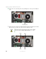
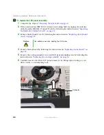
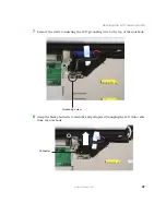
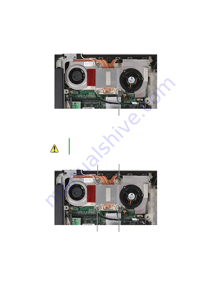
Remove the screw connecting the LCD grounding wire to the top of the number 4
screw.
7
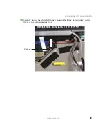
Remove the four screws that are stamped with the numbers 1 through 4 next to them.
Make sure that you remove the screws in reverse numerical order.
Caution
When removing the cooling assembly’s screws from the numbered
holes, remove them
in reverse numerical order
(4, 3, 2, then 1).
Grounding screw
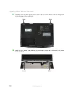
Screw
Screw
Screw
Screw
Summary of Contents for M520
Page 1: ......
Page 2: ......
Page 4: ...ii www gateway com ...
Page 13: ...9 www gateway com Replacing the memory module in the memory bay Memory bay ...
Page 18: ...14 www gateway com Replacing Gateway Notebook Components Mini PCI bay ...
Page 96: ...92 www gateway com Replacing Gateway Notebook Components ...
Page 97: ......


