IX
Table of Contents
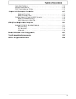
Intermittent Problems . . . . . . . . . . . . . . . . . . . . . . . . . . . . . . . . . . . . . . . . . . . . . . . .132
Undetermined Problems . . . . . . . . . . . . . . . . . . . . . . . . . . . . . . . . . . . . . . . . . . . . . .132
POST Code Reference Tables . . . . . . . . . . . . . . . . . . . . . . . . . . . . . . . . . . . . . . . . .133
Jumper and Connector Locations
137
Mainboard Top View . . . . . . . . . . . . . . . . . . . . . . . . . . . . . . . . . . . . . . . . . . . . .137
Mainboard Bottom View . . . . . . . . . . . . . . . . . . . . . . . . . . . . . . . . . . . . . . . . . .138
Clearing Password Check and BIOS Recovery . . . . . . . . . . . . . . . . . . . . . . . . . . . .139
Mainboard CMOS Discharge . . . . . . . . . . . . . . . . . . . . . . . . . . . . . . . . . . . . . .139
BIOS Recovery by Crisis Disk . . . . . . . . . . . . . . . . . . . . . . . . . . . . . . . . . . . . .140
FRU (Field Replaceable Unit) List
141
Gateway EC18/EC14 Exploded Diagrams . . . . . . . . . . . . . . . . . . . . . . . . . . . . . . . .141
Main Assembly . . . . . . . . . . . . . . . . . . . . . . . . . . . . . . . . . . . . . . . . . . . . . . . . .142
LCD Assembly . . . . . . . . . . . . . . . . . . . . . . . . . . . . . . . . . . . . . . . . . . . . . . . . .144
Screw List . . . . . . . . . . . . . . . . . . . . . . . . . . . . . . . . . . . . . . . . . . . . . . . . . . . . .150
Model Definition and Configuration
151
Test Compatible Components
155
Online Support Information
159
Summary of Contents for EC14
Page 6: ...VI ...
Page 10: ...X Table of Contents ...
Page 34: ...24 Chapter 1 ...
Page 50: ...40 Chapter 2 ...
Page 60: ...50 Chapter 3 5 Pull the memory module out ...
Page 71: ...Chapter 3 61 8 Lift up and pull the button board to main board FCC free ...
Page 89: ...Chapter 3 79 4 Lift the LCD panel out lifting the bottom of the panel first ...
Page 93: ...Chapter 3 83 5 Remove the antennas completely ...
Page 99: ...Chapter 3 89 3 Apply adhesive and stick the microphone down ...
Page 108: ...98 Chapter 3 3 Connect the speaker connector ...
Page 116: ...106 Chapter 3 5 Relay the WLAN cables around and through the lower case ...
Page 127: ...Chapter 3 117 4 Place the HDD cover in from one edge 5 Tighten the four captive screws ...
Page 130: ...120 Chapter 3 ...
Page 170: ...160 ...


