44
Chapter 3
External Module Disassembly Process
NOTE:
The product previews seen in the disassembly procedures may not represent the final product color or
configuration.
Screw List
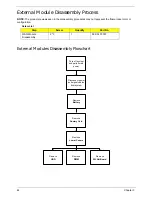
External Modules Disassembly Flowchart
Step
Screw
Quantity
Part No.
WAN Module
Disassembly
2*3
1
86.SA107.001
Disconnect power
and signal cables
from system
Remove
Dummy Card
Turn off system
and peripherals
power
Remove
DIMM
Remove
HDD
Remove
Lower Covers
Remove
WLAN Board
Remove
Battery
Summary of Contents for EC14
Page 6: ...VI ...
Page 10: ...X Table of Contents ...
Page 34: ...24 Chapter 1 ...
Page 50: ...40 Chapter 2 ...
Page 60: ...50 Chapter 3 5 Pull the memory module out ...
Page 71: ...Chapter 3 61 8 Lift up and pull the button board to main board FCC free ...
Page 89: ...Chapter 3 79 4 Lift the LCD panel out lifting the bottom of the panel first ...
Page 93: ...Chapter 3 83 5 Remove the antennas completely ...
Page 99: ...Chapter 3 89 3 Apply adhesive and stick the microphone down ...
Page 108: ...98 Chapter 3 3 Connect the speaker connector ...
Page 116: ...106 Chapter 3 5 Relay the WLAN cables around and through the lower case ...
Page 127: ...Chapter 3 117 4 Place the HDD cover in from one edge 5 Tighten the four captive screws ...
Page 130: ...120 Chapter 3 ...
Page 170: ...160 ...


