


Chapter 1
21
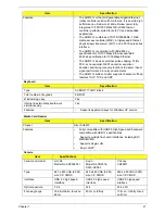
Keyboard
Media Card Reader
Camera
Features
•
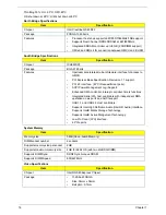
The AR8131L is the third generation Gigabit Ethernet
(GbE) controller solution from Atheros. It is an ultra-high
performance, ultralow cost, and ultra-low power fully
integrated 10/100/1000 Mbps NIC/LOM Ethernet
controller perfectly suited for both PC and embedded
applications.
•
The AR8131L combines a 10/100/1000BASE-T GbE
media access controller (MAC), a triplespeed Ethernet
physical layer transceiver (PHY), and a PCI Express bus
interface.
•
The AR8131L is compliant with IEEE 802.3u
specification for 10/100 Mbps Ethernet and IEEE
802.3ab specification for 1000 Mbps Ethernet.
•
The AR8131L device combines pulse shaping, Tx/Rx
PCS, echo canceller, NEXT canceller, equalizer,
decoder, and timing recovery functions to deliver robust
signal performance in noisy environments.
•
The AR8131L GbE controller supports checksum offload
features for IP, TCP, and UDP,
Item
Specification
Type
ACER NT1T JM11 Black
Total number of keypads
86/87/91
Windows logo key
Yes
Internal & external keyboard work
simultaneously
Yes
Features
•
Supports application keys for Windows XP version
Item
Specification
Chipset
Alcor AU6433
Features
•
Fully compatible with USB2.0 High Speed and backward
compatible with USB1.1 specifications
•
Supports multiple flash card interfaces, including SD/
MMC/xD/MS.
•
Supports single LUN
•
48-pin LQFP
Item
Specifications
Vendor and model
Lite On
Model No. 09P2SF001
Suyin
Model No.CN0316-
S30C-OV06-1
Chicony
CNF9011
Type
640 x 480 VGA (0.3M)
size 1/6” CMOS
640 x 480 VGA (0.3M)
size 1/6” CMOS
640 x 480 VGA (0.3M)
size 1/6” CMOS
Interface
USB 2.0 high speed
interface
USB 2.0 high speed
interface
USB 2.0 high speed
interface
Optical aperture
F2.4
F2.4
F2.4 ± 5%
Focusing range
18.65~Infinite, focus on
48cm
40 cm to Infinity
17.4cm ~ Infinity, focus
on 40cm
Item
Specification
Summary of Contents for EC14
Page 6: ...VI ...
Page 10: ...X Table of Contents ...
Page 34: ...24 Chapter 1 ...
Page 50: ...40 Chapter 2 ...
Page 60: ...50 Chapter 3 5 Pull the memory module out ...
Page 71: ...Chapter 3 61 8 Lift up and pull the button board to main board FCC free ...
Page 89: ...Chapter 3 79 4 Lift the LCD panel out lifting the bottom of the panel first ...
Page 93: ...Chapter 3 83 5 Remove the antennas completely ...
Page 99: ...Chapter 3 89 3 Apply adhesive and stick the microphone down ...
Page 108: ...98 Chapter 3 3 Connect the speaker connector ...
Page 116: ...106 Chapter 3 5 Relay the WLAN cables around and through the lower case ...
Page 127: ...Chapter 3 117 4 Place the HDD cover in from one edge 5 Tighten the four captive screws ...
Page 130: ...120 Chapter 3 ...
Page 170: ...160 ...