


Chapter 1
1
System Specifications
Features
Below is a brief summary of the computer’s many features:
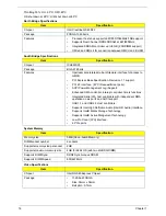
Operating System
•
Genuine Windows Vista ®
Platform
•
Intel® Core™2 Sol
•
Intel® Celeron® processor 723
•
Mobile Intel ® US15W Express Chipset
System Memory
•
Dual-channel DDR2 SDRAM support:
•
Up to 2 GB of DDR2 667 MHz memory, upgradeable to 4 GB using two soDIMM modules (for 32-
bit OS)
Display and graphics
•
11.6" HD 1366 x 768 pixel resolution, high-brightness (200-nit) Gateway Ultrabright™ TFT
LCD16:9 aspect ratio.
•
MPEG-2/DVD decodingWMV9 (VC-1) and H.264 (AVC) decodingHDMI™ (High-Definition
Multimedia Interface) with HDCP (High-bandwidth Digital Content Protection) support
Storage subsystem
•
2.5” 9.5mm 160 GB or larger hard disk drive
•
Multi-in-1 card reader
Audio subsystem
•
High-definition audio support
•
Two built-in stereo speakers
•
MS-Sound compatible
•
Built-in digital microphone
•
S/PDIF (Sony/Philips Digital Interface) support for digital speakers
Communication
•
IGateway Video Conference, featuring:, supporting 0.3-megapixel resolution
•
WLAN: Acer InviLink™ 802.11b/g Wi-Fi CERTIFIED® network connection, supporting Acer
SignalUp™ wireless technology
Chapter 1
Summary of Contents for EC14
Page 6: ...VI ...
Page 10: ...X Table of Contents ...
Page 34: ...24 Chapter 1 ...
Page 50: ...40 Chapter 2 ...
Page 60: ...50 Chapter 3 5 Pull the memory module out ...
Page 71: ...Chapter 3 61 8 Lift up and pull the button board to main board FCC free ...
Page 89: ...Chapter 3 79 4 Lift the LCD panel out lifting the bottom of the panel first ...
Page 93: ...Chapter 3 83 5 Remove the antennas completely ...
Page 99: ...Chapter 3 89 3 Apply adhesive and stick the microphone down ...
Page 108: ...98 Chapter 3 3 Connect the speaker connector ...
Page 116: ...106 Chapter 3 5 Relay the WLAN cables around and through the lower case ...
Page 127: ...Chapter 3 117 4 Place the HDD cover in from one edge 5 Tighten the four captive screws ...
Page 130: ...120 Chapter 3 ...
Page 170: ...160 ...