


88
www.gateway.com
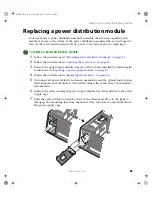
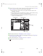
Chapter 4: Installing Components
10
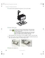
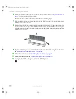
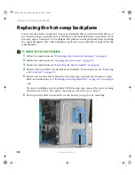
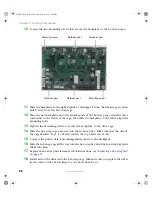
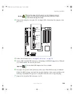
Loosen the two mounting screws that secure the backplane to the hot-swap cage.
11
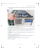
Slide the backplane to the right slightly to disengage it from the retainer posts, then
pull it away from the hot-swap cage.
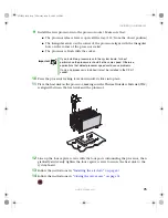
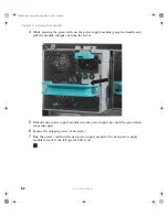
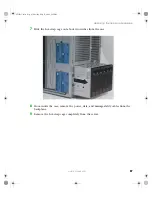
12
Place the new backplane onto the retainer posts of the hot-swap cage, with the drive
connectors to the inside of the cage, then slide the backplane to the left to align the
mounting holes.
13
Tighten the mounting screws to secure the backplane to the drive cage.
14
Slide the hot-swap cage part-way into the hot-swap bay. Make sure that the side of
the cage marked “Top” is oriented toward the top of the server case.
15
Connect the power, data, and manageability cables to the backplane.
16
Slide the hot-swap cage all the way into the hot-swap bay until the hot-swap bay latch
clicks into place.
17
Replace the hot-swap fan, if removed. For instructions, see
.
18
Install each of the drives into the hot-swap cage. Make sure that you replace the drives
in the correct order by referring to your notes from
.
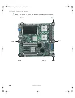
Mounting screw
Mounting screw
Retainer post
Retainer post
Retainer post
Retainer post
8510725.book Page 88 Tuesday, May 17, 2005 5:45 PM
Summary of Contents for 9510
Page 1: ...Gateway 9510 Server User Guide ...
Page 187: ...182 www gateway com Appendix A 8510725 book Page 182 Tuesday May 17 2005 5 45 PM ...
Page 213: ...208 www gateway com Appendix C 8510725 book Page 208 Tuesday May 17 2005 5 45 PM ...
Page 221: ...216 www gateway com 8510725 book Page 216 Tuesday May 17 2005 5 45 PM ...
Page 222: ...A MAN 9510 USR GDE R1 04 05 ...