background image

30

Chapter 3: Creating Disk Arrays

www.gateway.com

In cases where you are performing larger writes to the controller, you could 
go up to 2 MB for a stripe size, since you have more data to cluster. 

Never 

exceed 2 MB for a stripe size, since the controller cannot cluster over 
this size.

We recommend that you keep the stripe size to 1 MB or less for general 
use, perhaps increasing it for specific applications. This stripe size is 
actually the substripe size in RAID 50 cases. A 4+1 array (4 data and 1 parity 
drives) with a 256 K chunk has a 1 MB stripe size, as does an 8+1 array 
with 128 K stripe size, and an 8+2, RAID 50 array with 256 K chunk size.

Although 8+1 gives an even stripe size, this does not really matter for an 
operating system (OS) that writes in significantly smaller chunks. So, 8+1, 
10+1, or 11+1 with a chunk size of 64 K would be fine for an OS that does 
64 K writes. If the OS does much larger writes, you may want to increase 
the chunk size. With writeback cache enabled, the controller can keep data 
and do a full stripe write.

For a single enclosure example - best all around performance:

11+1 with 64 K chunk size would yield a 704 K stripe (11×64=704)

10+2 with 128 K chunk size would yield a 640 K stripe (5×128=640)

When using more drives, 14+2 (64 K), or 12+3 (128 K) should be as 
good as 12+4. However, we recommend that it be kept to a minimum 
of 4 data drives for a subarray.

For most sequential accesses, the difference may not be too much for 
different configurations. However, for large block random writes, it can 
help if the stripe size is similar to the I/O size. This lets the controller 
perform a partial full stripe write, where it has most of the data for a full 
stripe, and can just read some from the drives to complete the stripe.

While Windows NT, Windows 2000, and Windows 2003 do 64 K accesses, 
these are not aligned. If the chunk size is 64 K, every access crosses a chunk 
boundary and so involves two read/modify/write commands instead of 
one. However, since the controller can cluster, this problem is somewhat 
offset since the controller usually can cluster sufficiently to do full stripe 
writes. If it is a completely random 64 K access on Window NT, Windows 
2000, or Windows 2003, a 64 K chunk is not the best. A chunk size of 128 K 
or 256 K is better to minimize the number of commands that cross chunk.

Larger chunk sizes should be used if the OS is writing large blocks, or with 
large sequential writes where the controller can cluster sufficiently. Always 
keep the stripe size below 2 MB.

Summary of Contents for 840 VT-100

Page 1: ...Gateway 840VT 100 User s Guide Installing Getting Help ...

Page 2: ...lection for RAID 5 arrays 21 Creating arrays 22 Configuring array read ahead and writeback cache 36 Read ahead cache 36 Writeback cache 40 Assigning hot spare drives 47 Deleting an array 50 Expanding an array 53 Adding additional drives 54 Adding additional sub arrays 57 Trusting an array 61 4 Logical Drives 63 Overview 64 Terminology 64 Accessing the LUN configuration menu 66 Viewing unassigned f...

Page 3: ...ng the controller LUN 124 Setting the controller port ID 127 Controller port data rate 130 Setting the RS 232 configuration 133 Packetized data transfers QAS 136 Viewing controller information 138 Clearing the configuration 140 7 Additional Configuration 143 Modifying the configuration name 144 Verifying background media 147 Including enclosure events in event logs 150 8 Statistics 153 Overview 15...

Page 4: ...are 207 Drive maintenance 211 Download the firmware from the host 212 Checking RAID 5 50 parity 217 Tracing commands 220 Shutting down the controller 223 Dumping diagnostics 225 11 Optimizing RAID 5 Write Performance 227 Introduction 228 Sequential access 229 Number of outstanding commands 229 Access size 229 Access alignment 229 Using RAID 5 sub arrays 230 Experiencing multiple drive failures 231...

Page 5: ...iv ...

Page 6: ...alled in your Gateway 840 Series storage system The controllers are accessed through a VT 100 terminal using a menu based user interface connected directly to the RAID controllers This guide contains step by step procedures to access the VT 100 terminal utility as well as perform configuration functions and enclosure monitoring ...

Page 7: ...ystem by accessing the configuration utility locally This software guide provides the operational and reference information to configure and manage the SATA RAID controller installed in your Gateway 840 using this menu based user interface The following are some of the major features of local RAID configuration utility Simple straight forward user interface Menu based interface that works with a w...

Page 8: ...on line help provides a list of all the events that can occur along with a suggested cause and action to take When a warning or error event occurs you can review the event log locate the suspect event and see Event Logs on page 173 or help section to determine the possible cause or causes and the suggested action to take Also see Diagnostics on page 199 ...

Page 9: ...4 Chapter 1 Introduction www gateway com ...

Page 10: ...ration Utility This chapter provides information on accessing the configuration utility Read this chapter to learn how to Access the utility Use the VT 100 terminal Navigate the configuration utility View controller information ...

Page 11: ...to the RS 232 serial ports on the controller s rear panel Configure your terminal using the procedures described in Using the VT 100 terminal on page 7 Important You can also choose to use StorView Storage Management software to manage and monitor the enclosure and SATA RAID Controller Refer to the Gateway 840 SATA RAID StorView User s Guide for more information ...

Page 12: ... your host system or terminal RS 232 port to use the following settings Set the communications parameters for the terminal program as follows To access the RAID controllers 1 Connect the host terminal to the serial port on the controller using a null modem serial cable use the configuration information in the preceding tables 2 Turn on the terminal and the Gateway 840 Series storage system Setting...

Page 13: ...nal window press CTRL W The Main Menu opens You can now perform all of the functions described in the following chapters All steps begin from the Main Menu If an event or error occurs you can review the log for the problem by examining the event log see Event Logs on page 173 Important Make sure that your terminal emulation software is set to use the correct COM port on your computer ...

Page 14: ... menu system can be navigated using the keys on your keyboard The table below describes the primary navigation and selection methods To Do this Toggle interface from text base to menu based Press CTRL W keys Return to the previous menu or screen Exit Press the ESC key Move the selection Press the arrow keys Select a menu option Press the ENTER key ...

Page 15: ...ler information Clears All Configurations Additional Configuration View Array Create Array Delete Array Expand Array Array Cache Configuration View Unused Drives Advanced Array Configuration Array Configuration LUN Configuration Hardware Configuration LUN Management SAN LUN Mapping Controller LUN Port ID Settings Controller Port Data Rate RS232 Settings Packetized SCSI QAS Modify Configuration Nam...

Page 16: ...abled Rebuild Priority 50 LUN Management View Logical Drive Create Logical Drive Expand Logical Drive Set Availability Delete Logical Drive View Unassigned Free Space Modify Mapped LUN Number SAN LUN Mapping View SAN LUN Mappings Create SAN LUN Mapping Delete SAN LUN Mapping Modify SAN LUN Mapping View Connected Hosts Create Array Initialize Array Trust Array Displays Array Information Displays th...

Page 17: ...Both Ports View All Statistics View Access Statistics View Readahead Statistics View Command Clustering Statistics View Miscellaneous Statistics Clear Statistics View Access Statistics On Each Logical Drive Clear Access Statistics On Each Logical Drive View All Events View New Events View Last 50 Events View Last Hour Events View Last 24 Hours Events View Drive Port Events View Controller Port Eve...

Page 18: ...ler is available through the Main Menu and includes Controller World Wide Name WWN Firmware information Run time information Temperature and voltage information To view controller information 1 After the controller s have completed booting press CTRL E then press CTRL W to switch to the menu based mode The Main Menu opens ...

Page 19: ...er is present only one selection is listed The following is a brief summary of the information displayed Item Description Controller WWN An 8 byte unique World Wide Name the controller uses for identification This is unique to each controller and preprogrammed Configuration WWN An 8 byte World Wide Name the controller uses for identification to hosts This can be identical to the Controller WWN or ...

Page 20: ...powered on Current Power on Time The length of time since this controller has last been powered on or reset Current Controller Time This is the current time on the controller Last Configuration Time This is the time the controller was last configured Onboard Temperature This is the current temperature as measured by the controller If this value exceeds predefined limits an event will be written in...

Page 21: ...16 Chapter 2 Accessing the Configuration Utility www gateway com ...

Page 22: ...apter provides information on creating disk arrays Read this chapter to learn how to Understand arrays Create arrays Configure array read ahead and writeback cache Assign hot spare drives Delete an array Expand an array Trust an array ...

Page 23: ... 840 SATA RAID Enclosure User s Guide This chapter will step you through the process to create the disk arrays You will also find sections on deleting arrays expanding arrays and assigning hot spare drives You are then directed to the next chapter for the procedures to define the logical drives which makes the drive array s available to the operating system This manual assumes you have a basic und...

Page 24: ...iple LUNs or have an option for it If your operating system does not support multiple LUNs the host will only be able to see one array at the first disk LUN Term Description Array A group of drives that are combined together to create a single large storage area Up to 64 arrays are supported each containing up to 12 drives per array There is no limit for the drive size in the arrays Chunk Size Thi...

Page 25: ...ve parallelism increases throughput because all drives in the stripe set work together on every I O operation For greatest efficiency all drives in the stripe set must be the same capacity Because all drives are used in every operation RAID 0 allows for single threaded I O only i e one I O operation at a time Environments with many small simultaneous transactions e g order entry systems will not g...

Page 26: ...ng RAID 5 Write Performance on page 227 Additional information is provided at the appropriate step during configuration RAID Level 10 RAID 10 is defined as mirrored stripe sets also known as RAID 0 1 You can build RAID 10 either directly through the RAID controller depending on the controller or by combining software mirroring and controller striping called RAID 01 RAID Level 50 This RAID level is...

Page 27: ...anges are made until the configuration is saved so it is possible to quit at any time without affecting the current configuration as long as you do not save those changes Configuration can be performed while the system is active Important We recommend that you make notes about the arrays you create in case you need to duplicate the configuration for an array See Trusting an array on page 61 Import...

Page 28: ...23 Creating arrays www gateway com To view an array 1 From the Main Menu select Configuration Menu then press ENTER The Configuration Menu opens ...

Page 29: ...he fields shown on the screen 3 Press ESC to return to the previous screen Field Description No Drive number in the array Vendor ID Indicates the manufacturer of the drive Product ID Drive model number F W Drive firmware version Ser No Drive serial number Cap Drive capacity expressed in GBs EN SL The enclosure and drive slot number used for drive identification ST The drive status will either be O...

Page 30: ...25 Creating arrays www gateway com To create an array 1 From the Main Menu select Configuration Menu then press ENTER The Configuration Menu opens ...

Page 31: ...s www gateway com 2 To access the Array Configuration Menu select Array Configuration then press ENTER The Array Configuration Menu opens The Array Configuration Menu lets you review create delete or otherwise modify the active arrays ...

Page 32: ...27 Creating arrays www gateway com 3 From the Array Configuration Menu select Create Array then press ENTER The Array Name screen opens ...

Page 33: ...Disk Arrays www gateway com 4 Type a name for the array using as many as 32 characters then press ENTER The RAID Level screen opens 5 Highlight the appropriate RAID level then press ENTER The Configuration Type screen opens ...

Page 34: ...n page 227 for detailed information The primary aim of setting a chunk size is to try to set a stripe size that allows for full stripe writes The stripe size is determined by the number of data drives multiplied times the chunk size 8 data drives 64 K chunk size 512 strip size For maximum performance with RAID 5 50 arrays you want to do as many full stripe writes as possible Typically Windows NT W...

Page 35: ... 11 64 704 10 2 with 128 K chunk size would yield a 640 K stripe 5 128 640 When using more drives 14 2 64 K or 12 3 128 K should be as good as 12 4 However we recommend that it be kept to a minimum of 4 data drives for a subarray For most sequential accesses the difference may not be too much for different configurations However for large block random writes it can help if the stripe size is simil...

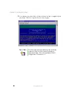
Page 36: ... a drive to the array by highlighting the drive then pressing the U key Or you can select all the available drives by pressing the A key Remove a drive that has been selected by pressing the R key or remove all of the drives selected by pressing the C key Tips Tricks If you have multiple enclosures the enclosure you are viewing is displayed at the top of the page To move to the drives in the next ...

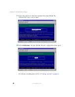
Page 37: ...s when you have completed your selections The Drive Capacity Reserve screen opens Tips Tricks The drive capacity reserve determines how much drive capacity to retain for future capacity fluctuations of replacement drives This is not applicable to RAID 0 configurations The default is 1 ...

Page 38: ...rrays that provides two four drive sub arrays with one parity drive When you create a redundant array such as a RAID 5 or 50 type you will always be creating at least one sub array comprised of the data drives and one parity drive When a sufficient number of drives have been selected you can choose to make multiple sub arrays of your array This provides the benefits of a quicker recovery from a dr...

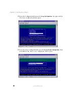
Page 39: ... 11 Select the number of sub arrays required then press ENTER The Initialize Trust Arrays screen opens 12 Select Initialize Array then press ENTER The Save Configuration screen opens For details on trusting arrays refer to Trusting an array on page 61 ...

Page 40: ... up the Array Read Ahead Cache and Writeback Cache then go to the Hot Spare drives options Important You must initialize the array before using the logical drives created from the array Tips Tricks After you have completed these tasks go to the next chapter Create the logical drives and perform the LUN assignment to complete the setup Additionally for more control over the logical drives see SAN L...

Page 41: ... improves the data retrieval performance by allowing the controller to read into cache a full stripe of data at one time which greatly improves the cache hits For smaller transfers the Read Ahead algorithm can improve performance If for example the stripe size is 256 KB chunk size multiplied by the number of data drives and the host requests 64 KB of data when Read Ahead is enabled the controller ...

Page 42: ...37 Configuring array read ahead and writeback cache www gateway com To configure the read ahead cache 1 From the Main Menu select Configuration Menu then press ENTER The Configuration Menu opens ...

Page 43: ...way com 2 From the Configuration Menu select Array Configuration then press ENTER The Array Configuration Menu opens 3 From the Array Configuration Menu select Array Cache Configuration then press ENTER The Array Cache Configuration Menu opens ...

Page 44: ...iguration Menu select Read Ahead Cache then press ENTER The Select Array screen opens 5 Press the up or down arrow keys to select an array then press ENTER 6 Press the up and down arrow keys to select a Read Ahead Cache parameter to use for the selected array then press CTRL D to save the changes ...

Page 45: ...her If sufficient data is sent to fill a stripe in RAID 5 50 configurations the controller can perform a full stripe write which significantly reduces the write overhead associated with RAID 5 50 Disabling writeback cache ensures that the data is sent to the drives before status is returned to the host With writeback cache enabled if a short term power failure occurs the battery back up unit provi...

Page 46: ... but can lower simultaneous read performance The recommended size is 16 MB The strategy of write operations results in a completion signal being sent to the host operating system as soon as the cache receives the data to be written The hard drives will receive the data at a more appropriate time in order to increase controller performance Configuration Memory Vendor and Part Number Measured Curren...

Page 47: ...42 Chapter 3 Creating Disk Arrays www gateway com To configure the writeback cache 1 From the Main Menu select Configuration Menu then press ENTER The Configuration Menu opens ...

Page 48: ...ww gateway com 2 From the Configuration Menu select Array Configuration then press ENTER The Array Configuration Menu opens 3 From the Array Configuration menu select Array Cache Configuration Menu then press ENTER The Array Cache Configuration Menu opens ...

Page 49: ...44 Chapter 3 Creating Disk Arrays www gateway com 4 From the Array Cache Configuration Menu select Writeback Cache then press ENTER The Writeback Parameters Select Array menu opens ...

Page 50: ...t the cache and the left and right arrow keys to toggle from Disabled to Enabled or choose one of the pre determined cache threshold sizes 1 MB 2 MB 4 MB 8 MB 16 MB 32 MB 64 MB 128 MB or 256 MB There are three additional options to an active Write Back Cache Disable if a partner controller fails or is missing Disable if a controller battery fails or Disable if the array is in a critical state for ...

Page 51: ...apter 3 Creating Disk Arrays www gateway com 7 Press CTRL D to save the changes The Save Configuration screen opens 8 Select Yes to save the configuration changes then press ENTER 9 Press any key to continue ...

Page 52: ...nt of a drive failure the controller will use a global hot spare to replace the failed drive in any array If a dedicated spare is assigned to the specific array that array will use its dedicated hot spare This step is accomplished through the Hot Spare Configuration menu To configure hot spare drives 1 From the Main Menu select Configuration Menu then press ENTER The Configuration Menu opens ...

Page 53: ...ess the up or down arrow keys to select Hot Spare Configuration menu then press ENTER The Hot Spare Configuration Menu opens 3 To add or remove a hot spare drive select Add or Remove Pool and Dedicated Spare then press ENTER The Add or Remove Global and Dedicated Spares screen opens ...

Page 54: ...ool spare global press the arrow keys to highlight an available drive and press H To remove a drive as a hot spare highlight the subject drive and press R or press C to remove all drives in the enclosure that are currently assigned as spares 5 After you make your selection press CTRL D to continue 6 When you are prompted to save the changes press Y to save the new hot spare configurations 7 Press ...

Page 55: ...50 Chapter 3 Creating Disk Arrays www gateway com Deleting an array To delete an array 1 From the Main Menu select Configuration Menu then press ENTER The Configuration Menu opens ...

Page 56: ...ateway com 2 From the Configuration Menu select Array Configuration Menu then press ENTER The Array Configuration Menu opens 3 From the Array Configuration Menu select Delete Array then press ENTER The Delete Array screen opens ...

Page 57: ...pter 3 Creating Disk Arrays www gateway com 4 Press the up and down arrow keys to select the array to delete then press ENTER 5 To complete the deletion select Yes then press ENTER 6 Press any key to continue ...

Page 58: ...rives 3 1 which indicates the array sub array is composed of 4 drives of which 3 are data drives and 1 is a parity drive If you were to add 1 sub array to this particular configuration the resulting display would be 8 Drives 6 2 in which case you now have 6 data drives and 2 parity drives Your RAID 5 array now becomes a RAID 50 array because it s composed of two sub arrays each sub array has three...

Page 59: ...54 Chapter 3 Creating Disk Arrays www gateway com Adding additional drives To add additional drives 1 From the Main Menu select Configuration Menu then press ENTER The Configuration Menu opens ...

Page 60: ...way com 2 From the Configuration Menu select Array Configuration Menu then press ENTER The Array Configuration Menu opens 3 From the Array Configuration Menu select Expand Array then press ENTER The Select Array to Expand Menu opens ...

Page 61: ...ay com 4 Press the up and down arrow keys to select an array to expand then press ENTER The Expansion menu opens 5 From the Expansion menu select Add a Number of Drives to the Array then press ENTER The Expand Array Drive Selection screen opens ...

Page 62: ...s CTRL D to continue You can cancel your selection by highlighting the drive and pressing R or remove all selected drives and start again by pressing C 7 When you are prompted to save the changes select Yes then press ENTER 8 Press any key to continue Adding additional sub arrays To add additional sub arrays 1 From the Main Menu select Configuration Menu then press ENTER The Configuration Menu ope...

Page 63: ...w gateway com 2 From the Configuration menu select Array Configuration Menu then press ENTER The Array Configuration Menu opens 3 From the Array Configuration Menu select Expand Array then press ENTER The Select Array to Expand Menu opens ...

Page 64: ... up and down arrow keys to select an array to expand then press ENTER The Expansion Menu opens 5 Press the up and down arrow keys to select Add a Number of Sub Arrays to the Current Array then press ENTER The Expand Array Drive Selection screen opens ...

Page 65: ...ive for expansion Continue to select additional drives if necessary otherwise press CTRL D to continue You can cancel your selection by highlighting the drive and pressing R or remove all selected drives and start again by pressing C 7 When you are prompted to save the changes select Yes then press ENTER 8 Press any key to continue ...

Page 66: ...s all drives and therefore there is no known state on the drives As data is received from the host parity is calculated as normal but it occurs on a block basis There is no way to guarantee that parity has been calculated across the entire drive The parity data will be inconsistent so a drive failure within a trusted array will cause data loss To trust an array 1 When creating a RAID 5 50 array af...

Page 67: ...Chapter 3 Creating Disk Arrays www gateway com 3 You are prompted to save the configuration Select Yes to save the configuration then press ENTER 4 After the process has completed press any key to continue ...

Page 68: ...l Drives This chapter provides information on creating logical drives Read this chapter to learn how to Configure a logical drive Access the LUN configuration menu View unassigned free space Create a logical drive ...

Page 69: ...e than one logical drive you must be sure that your host HBA and host operating system is setup to handle the desired number of logical drives LUNs or Logical Unit Numbers If your operating system does not support multiple logical drives the host will only be able to see the first logical drive Important For Microsoft Windows NT there is a limitation of 231 logical drives A hot fix is available fr...

Page 70: ...sirable to change the number of the logical drive This can be done at any time bearing in mind that any attached host systems may need to be rebooted or reconfigured to retain access Unassigned Free Space The controller keeps a map of all the space that is not assigned to any logical drive This space is available for logical drive creation or expansion Each unassigned region is individually listed...

Page 71: ...hapter 4 Logical Drives www gateway com Accessing the LUN configuration menu To access the LUN configuration menu 1 From the Main Menu select Configuration Menu then press ENTER The Configuration Menu opens ...

Page 72: ...then press ENTER The LUN Configuration Menu opens The LUN Configuration Menu has two menu options one for managing logical drives which includes utilities for viewing creating deleting and managing LUNs and the other is for performing SAN LUN mapping operations For more information see SAN LUN Mapping on page 89 ...

Page 73: ...igned free space This will help you to identify the unused regions or segments for use during the creation of your logical drives Normally with a first time configuration this is not necessary since all of the space is unassigned To view unassigned free space 1 From the Main Menu select Configuration Menu then press ENTER The Configuration Menu opens ...

Page 74: ...space www gateway com 2 From the Configuration Menu select LUN Configuration then press ENTER The LUN Configuration Menu opens 3 From the LUN Configuration Menu select LUN Management then press ENTER The LUN Management Menu opens ...

Page 75: ...4 Logical Drives www gateway com 4 From the LUN Management Menu select View Unassigned Free Space then press ENTER The Unassigned Free Space screen opens 5 Review the free space regions and note them for later use ...

Page 76: ...ring your arrays you will need to create one or more logical drives Creating a logical drive from the available free space regions presents the logical drive to the host operating system To create a logical drive 1 From the Main Menu select Configuration Menu then press ENTER The Configuration Menu opens ...

Page 77: ...es www gateway com 2 From the Configuration menu select LUN Configuration then press ENTER The LUN Configuration Menu opens 3 From the LUN Configuration menu select LUN Management then press ENTER The LUN Management Menu opens ...

Page 78: ...N Management menu select Create Logical Drive then press ENTER The Select Unused Region Menu opens 5 Press the up and down arrow keys to select a region you want to use for the logical drive then press ENTER The Number of Logical Drives to create screen opens ...

Page 79: ...nused space from which another separate logical drive can be created For example if you have a fault tolerant array with unused region of 143 GB and you create 2 logical drives from that unused space you will have two logical drives each with 71 GBs After you create the logical drives and view the unused region you will see the remaining 1 GB available for use in another logical drive 8 When you a...

Page 80: ...75 Creating a logical drive www gateway com Expanding a logical drive To expand a LUN 1 From the Main Menu select Configuration Menu then press ENTER The Configuration Menu opens ...

Page 81: ...es www gateway com 2 From the Configuration menu select LUN Configuration then press ENTER The LUN Configuration Menu opens 3 From the LUN Configuration Menu select LUN Management then press ENTER The LUN Management Menu opens ...

Page 82: ...teway com 4 From the LUN Management menu select Expand Logical Drive then press ENTER The Select Logical Drive screen opens 5 Select a logical drive that you want to expand then press ENTER The Unused Regions For Expansion screen opens ...

Page 83: ...t to expand the logical drive then press ENTER The Expansion Size screen opens 7 Press the up and down arrow keys to change the value to the desired size then press ENTER 8 When you are prompted to save the configuration select Yes then press ENTER 9 Press any key to return to the Main Menu ...

Page 84: ...l make a logical drive available to a controller port and determines whether that logical drive is seen by all or a specific host system attached to that controller port To set logical drive availability 1 From the Main Menu select Configuration Menu then press ENTER The Configuration Menu opens ...

Page 85: ...es www gateway com 2 From the Configuration menu select LUN Configuration then press ENTER The LUN Configuration Menu opens 3 From the LUN Configuration menu select LUN Management then press ENTER The LUN Management Menu opens ...

Page 86: ...ogical Drive for Availability screen select a logical drive that you want to map to another LUN number then press ENTER The Modify the Logical Drive Availability screen opens 6 From the Modify the Logical Drive Availability screen select the controller port to modify Press ENTER to change the property from Enable to Disable 7 If necessary repeat the step to change the availability of the other por...

Page 87: ...d to save the configuration select Yes then press ENTER 10 Press any key to return to the Main Menu Deleteing a logical drive This process will remove an existing logical drive To delete a logical drive 1 From the Main Menu select Configuration Menu then press ENTER The Configuration Menu opens ...

Page 88: ...ve www gateway com 2 From the Configuration menu select LUN Configuration then press ENTER The LUN Configuration Menu opens 3 From the LUN Configuration menu select LUN Management then press ENTER The LUN Management Menu opens ...

Page 89: ... Drive then press ENTER The Select a Logical Drive to Delete screen opens 5 From the Select a Logical Drive to Delete screen select the logical drive to delete then press ENTER 6 When you are prompted to save the configuration select Yes then press ENTER 7 Press any key to return to the Main Menu ...

Page 90: ...difying a mapped LUN This option lets you change the assigned LUN number after the logical drive has previously been made available To modify a LUN number 1 From the Main Menu select Configuration Menu then press ENTER The Configuration Menu opens ...

Page 91: ...es www gateway com 2 From the Configuration menu select LUN Configuration then press ENTER The LUN Configuration Menu opens 3 From the LUN Configuration menu select LUN Management then press ENTER The LUN Management Menu opens ...

Page 92: ...dify Mapped LUN Number then press ENTER The Select a Logical Drive to Modify Mapped Number screen opens 5 From the Select a Logical Drive to Modify Mapped Number screen select the logical drive whose number you intend to change then press ENTER The Select a New LUN Number screen opens ...

Page 93: ...way com 6 Press the up and down arrow keys to change the logical drive number to the desired number then press ENTER 7 When you are prompted to save the configuration select Yes then press ENTER 8 Press any key to return to the Main Menu ...

Page 94: ...rovides information on SAN LUN mapping Read this chapter to learn how to Access the SAN LUN mapping configuration menu View SAN LUN mappings Create a SAN LUN mapping Delete a SAN LUN mapping Modify a SAN LUN mapping View connected hosts ...

Page 95: ...and two additional bytes which are used to specify the format Port Name This is an eight byte hexadecimal number uniquely identifying a single host port It incorporates the World Wide Name and two additional bytes which are used to specify the format and indicate the port number Mapping Name A 32 character name that can be used to help identify the host system Exclusive Access A logical drive is p...

Page 96: ...ng configuration menu www gateway com Accessing the SAN LUN mapping configuration menu To access the SAN LUN mapping configuration menu 1 From the Main Menu select the Configuration Menu then press ENTER The Configuration Menu opens ...

Page 97: ... The LUN Configuration Menu opens 3 From the LUN Configuration menu select SAN LUN Mapping then press ENTER The SAN LUN Mapping screen opens The SAN LUN Mapping Configuration Menu provides the options for viewing creating deleting and managing SAN LUNs and for viewing the host systems attached to the storage network ...

Page 98: ...ppings www gateway com Viewing SAN LUN mappings To view existing SAN LUN mappings choose this option To view SAN LUN mappings 1 From the Main Menu select the Configuration Menu then press ENTER The Configuration Menu opens ...

Page 99: ...g www gateway com 2 From the Configuration menu select LUN Configuration then press ENTER The LUN Configuration Menu opens 3 From the LUN Configuration menu select SAN LUN Mapping then press ENTER The SAN LUN Mapping screen opens ...

Page 100: ... drive exclusively The following information is shown on the screen Mapping Name This is the name defined by the user when creating the SAN LUN Mapping You may use up to 32 ASCII characters HBA SCSI ID This is initiator target SCSI ID of the host system HBA port used for the mapping Port This is the port of the RAID Controller The controller has two ports and will be listed here as 0 and 1 They re...

Page 101: ...96 Chapter 5 SAN LUN Mapping www gateway com Creating a SAN LUN mapping To create a SAN LUN mapping 1 From the Main Menu select the Configuration Menu then press ENTER The Configuration Menu opens ...

Page 102: ...g www gateway com 2 From the Configuration menu select LUN Configuration then press ENTER The LUN Configuration Menu opens 3 From the LUN Configuration menu select SAN LUN Mapping then press ENTER The SAN LUN Mapping screen opens ...

Page 103: ...4 From the SAN LUN Mapping Menu select Create SAN LUN Mapping then press ENTER The SAN LUN Mapping Name screen opens 5 Type a unique name for this mapping as many as 32 characters then press ENTER The SAN LUN Mapping Configuration screen will open ...

Page 104: ...e here for selection If the logical drive was mapped as Share or Shared Read Only it will be available 6 When you are prompted to save the configuration select Yes then press ENTER 7 Press any key to return to the Main Menu Important Microsoft Windows NT Microsoft Windows 2000 and Microsoft Windows 2003 do not support a Read Only file system ...

Page 105: ...100 Chapter 5 SAN LUN Mapping www gateway com Deleting a SAN LUN mapping To delete a SAN LUN mapping 1 From the Main Menu select the Configuration Menu then press ENTER The Configuration Menu opens ...

Page 106: ...ng www gateway com 2 From the Configuration Menu select LUN Configuration then press ENTER The LUN Configuration Menu opens 3 From the LUN Configuration Menu select SAN LUN Mapping then press ENTER The SAN LUN Mapping screen opens ...

Page 107: ... Select a SAN LUN Mapping to be deleted then press ENTER 6 When you are prompted to save the configuration select Yes then press ENTER 7 Press any key to return to the Main Menu 8 Access your host operating system and make the necessary adjustments for the change in disk s Tips Tricks SAN LUN Mappings can be deleted in any order without affecting the other mappings ...

Page 108: ... Mapping Name Port Name and the RAID controller port availability access of the mapping This may be necessary if for example a host system has an adapter failure and a new adapter with different Node and Port names initiator ID for SCSI HBAs is installed To modify a SAN LUN mapping 1 From the Main Menu select the Configuration Menu then press ENTER The Configuration Menu opens ...

Page 109: ...g www gateway com 2 From the Configuration menu select LUN Configuration then press ENTER The LUN Configuration Menu opens 3 From the LUN Configuration menu select SAN LUN Mapping then press ENTER The SAN LUN Mapping screen opens ...

Page 110: ...m the SAN LUN Mapping menu select Modify SAN LUN Mapping then press ENTER The Modify SAN LUN Mapping screen opens 5 Press the up and down arrow keys to select a SAN LUN Mapping to be modified then press ENTER The Modify SAN LUN Mapping Name screen opens ...

Page 111: ...l drives If a logical drive is already part of another mapping and is defined as Exclusive it will not be available here for selection If the logical drive was mapped as Share or Shared Read Only it will be available Press CTRL D to move to the next menu 8 You are presented with modifying the controller LUN for the mapping You can choose to leave the property in the automatic mode or set an exclus...

Page 112: ...107 Modifying SAN LUN Mapping www gateway com 9 When you are prompted to save the configuration select Yes then press ENTER 10 Press any key to return to the Main Menu ...

Page 113: ...Mapping www gateway com Viewing connected hosts Choose this option to view all connected host HBA ports To view connected hosts 1 From the Main Menu select the Configuration Menu then press ENTER The Configuration Menu opens ...

Page 114: ... www gateway com 2 From the Configuration menu select LUN Configuration then press ENTER The LUN Configuration Menu opens 3 From the LUN Configuration menu select SAN LUN Mapping then press ENTER The SAN LUN Mapping screen opens ...

Page 115: ...TER The View Logged in Hosts screen opens The following table provides an explanation of each of the fields shown in the display Field Description No Host number assigned by the controller This is used when creating a SAN LUN Mapping and selecting a host from the list SCSI ID This is the SCSI ID of the host bus adapter ...

Page 116: ...gement This chapter provides information on advanced configuration and management Read this chapter to learn how to Set rebuild parameters Configure hot spares Configure hardware settings View controller information Clear the configuration ...

Page 117: ...er a hot spare is created whether it is a global or dedicated spare for the specific array the automatic rebuild feature is enabled However there may be occasions where it is necessary to manually enable or disable this option When enabled auto regeneration will begin the rebuild cycle when a fault tolerant array is configured a hot spare drive is available and a drive fault occurs To enable or di...

Page 118: ...ct the Auto Rebuild and Set Priority option then press ENTER The Auto Rebuild and Set Priority menu opens From the Auto Rebuild and Set Priority menu you have the option to enable the automatic rebuild or set the percent of processor time allocated to a rebuild operation 4 Press ENTER to Enable or Disable Auto Rebuild Then press the up and down arrow keys to change the rebuild priority value ...

Page 119: ...L D to save the changes and continue 6 When you are prompted to confirm the save choose Yes then press ENTER 7 Press any key to return to the Main Menu Important The values range from 10 through 90 The higher the value the more processor time is allocated to the rebuild operation ...

Page 120: ...matically start a rebuild operation when a replacement drive is inserted into the drive slot of the removed failed drive member This feature only applies when a dedicated or pool spare has not been assigned To configure an auto hot spare 1 From the Main Menu select Configuration Menu then press ENTER The Configuration Menu opens ...

Page 121: ...agement www gateway com 2 From the Configuration Menu select Rebuild Parameters then press ENTER The Rebuild Parameters Menu opens 3 From the Rebuild Parameters Menu select the Auto Hot Spare option then press ENTER The Auto Hot Spare Menu opens ...

Page 122: ...etween Enable or Disable Enabling this feature will automatically start a rebuild operation when a replacement drive is inserted into the drive slot of the removed failed drive member 5 Press CTRL D to save the changes or press ESC to cancel and return to the previous menu ...

Page 123: ...hat is a member of a fault tolerant array the controller will use an assigned global hot spare to replace the failed drive in any array If a dedicated spare is assigned to the specific array that array will use its dedicated hot spare to replace the failed drive member Viewing the list of hot spare drives To view a list of hot spare drives 1 From the Main Menu select Configuration Menu then press ...

Page 124: ...119 Configuring hot spares www gateway com 2 From the Configuration menu select Hot Spare Configuration then press ENTER The Hot Spare Configuration menu opens ...

Page 125: ...120 Chapter 6 Advanced Configuration and Management www gateway com 3 Select View Hot Spare Drive Configuration then press ENTER A list of hot spare drives opens ...

Page 126: ...1 Configuring hot spares www gateway com Adding or removing hot spare drives To add or remove hot spare drives 1 From the Main Menu select Configuration Menu then press ENTER The Configuration Menu opens ...

Page 127: ...w gateway com 2 From the Configuration menu select Hot Spare Configuration then press ENTER The Hot Spare Configuration menu opens 3 Select Add or Remove Global and Dedicated Spare then press ENTER The Add or Remove Global and Dedicated Spares screen opens ...

Page 128: ...n the dedicated spare To add a drive as a global spare press the arrow keys to select an available drive then press H key To remove a drive as a hot spare select the drive then press R or press C to remove all drives in the enclosure that are currently assigned as spares After the changes have been made press the CTRL D to continue 5 When you are prompted to save the changes press Y to save the ne...

Page 129: ... automatically use the next available data LUN to communicate between StorView and the SATA RAID Controller We recommend that this setting remain in the automatic mode Changing this parameter can alleviate a potential issue that some operating systems have with a controller showing up at the end of the data LUNs In the event you have an operating system that is having a problem with the controller...

Page 130: ...com To configure the controller LUN 1 From the Main Menu select Configuration Menu then press ENTER The Configuration Menu opens 2 From the Configuration Menu select Hardware Configuration then press ENTER The Hardware Configuration Menu opens ...

Page 131: ...d of Controller LUN assignment 5 Press CTRL D to save the changes and continue 6 When you are prompted to confirm the save choose Yes then press ENTER 7 Press any key to return to the Main Menu Important If you chose User Defined a specific LUN value is displayed and selected by the up or down arrow keys If you select a LUN number that is used by another device the word Conflict will appear next t...

Page 132: ...e controller port ID The Port ID settings provide you the option to set the SCSI ID for the controller port You can use IDs 0 15 To set the ID for controller ports 1 From the Main Menu select Configuration Menu then press ENTER The Configuration Menu opens ...

Page 133: ...2 From the Configuration Menu select Hardware Configuration then press ENTER The Hardware Configuration Menu opens 3 From the Hardware Configuration Menu select Port ID Settings then press ENTER The Port ID Menu opens 4 Press ENTER to toggle between Disabled and Enabled ...

Page 134: ...lt IDs for the controller ports are Port 0 ID 4 and Port 1 ID 5 5 Press CTRL D to save the changes and continue 6 When you are prompted to confirm the save choose Yes then press ENTER 7 Press any key to return to the Main Menu Important IDs can only be changed when there is a RAID configuration present ...

Page 135: ...ontroller port data rate This option lets you set the data transfer rate of the controller ports The settings include 320 MB 160 MB and 80 MB To set the controller port data rate 1 From the Main Menu select Configuration Menu then press ENTER The Configuration Menu opens ...

Page 136: ...om 2 From the Configuration Menu select Hardware Configuration then press ENTER The Hardware Configuration Menu opens 3 From the Hardware Configuration Menu select Controller Port Data Rate then press ENTER The Control Port Data Rate Menu opens ...

Page 137: ...s to choose a controller port then press ENTER The Host Port Data Rate Options screen opens 5 Use the up and down arrow keys to select 320MB sec 160MB sec or 80 MB sec then press ENTER 6 When you are prompted to confirm the change choose Yes then press ENTER 7 Press any key to return to the Main Menu ...

Page 138: ... the RS 232 configuration The RS 232 Settings option provides you with the option to set the BAUD rate for the controller s RS 232 port To change RS 232 settings 1 From the Main Menu select Configuration Menu then press ENTER The Configuration Menu opens ...

Page 139: ...ment www gateway com 2 From the Configuration Menu select Hardware Configuration then press ENTER The Hardware Configuration Menu opens 3 From the Hardware Configuration Menu select RS 232 Settings then press ENTER The Baud Rate Selection Menu opens ...

Page 140: ...p and down arrow keys to select a BAUD rate for the controller RS 232 port the default and recommended setting is 115 200 then press ENTER 5 When you are prompted to save the configuration select Yes then press ENTER 6 Press any key to return to the Main Menu ...

Page 141: ...that are protected with a CRC These packets are also sent synchronously to reduce the protocol overhead This option is set Enabled by default for 320 MB sec data rates and is required for 320 MB sec operations To set the packetized protocol 1 From the Main Menu select Configuration Menu then press ENTER The Hardware Configuration Menu opens Tips Tricks The default setting of Enabled should be vali...

Page 142: ...ta Transfers Using QAS then press ENTER The Packetized SCSI QAS screen opens 3 Press the up or down arrow keys to select Enabled or Disabled 4 Press CTRL D to save the changes and continue 5 When you are prompted to confirm the save choose Yes then press ENTER 6 Press any key to return to the Main Menu ...

Page 143: ...the ability to view detailed information on the SATA RAID Controller such as Controller WWN Configuration WWN and Name Firmware run time data and onboard temperature and voltage information To view controller information 1 From the Main Menu select Controller Information then press ENTER The Select Controller Menu opens ...

Page 144: ... and down arrow keys to select a Controller then press ENTER The Controller Information screen opens 3 Use U and D to scroll up and down through the controller information displayed If you want to capture the information press P to dump the data to a text file 4 Press ESC to return to the previous menu ...

Page 145: ...apter 6 Advanced Configuration and Management www gateway com Clearing the configuration To clear the configuration 1 From the Main Menu select Configuration Menu then press ENTER The Configuration Menu opens ...

Page 146: ...lear Configuration then press ENTER The Clear Configuration Warning opens 3 Press Y to continue and clear all configuration information or N to cancel this operation 4 Press ESC to return to the Main Menu Caution There is no further warning clearing the configuration will erase all data ...

Page 147: ...142 Chapter 6 Advanced Configuration and Management www gateway com ...

Page 148: ...chapter provides information on additional configuration Read this chapter to learn how to Modify configuration names Modify configuration WWNs Set single controller mode Verify background media Include enclosure events in the event logs ...

Page 149: ...apter 7 Additional Configuration www gateway com Modifying the configuration name To modify the configuration name 1 From the Main Menu select Configuration Menu then press ENTER The Configuration Menu opens ...

Page 150: ...y com 2 From the Configuration menu select Additional Configuration then press ENTER The Additional Configuration Menu opens 3 Press the up and down arrow keys to select Modify Configuration Name then press ENTER The Configuration Name screen opens ...

Page 151: ...lete the existing Configuration Name displayed type a new name for your controller s Configuration as many as 64 ASCII characters then press ENTER to continue 5 When you are prompted to save the configuration select Yes then press ENTER 6 Press any key to return to the Main Menu ...

Page 152: ...atically verify the media of all drives in the background If a media error is detected the controller can automatically re write the data providing that the array is in a fault tolerant mode To verify background media 1 From the Main Menu select Configuration Menu then press ENTER The Configuration Menu opens ...

Page 153: ...ion then press ENTER The Additional Configuration Menu opens 3 From the Additional Configuration Menu select Background Verification then press ENTER The Background Verification screen opens 4 Press ENTER to toggle between Enabled or Disabled Background Verification 5 Press CTRL D to continue and save the changes ...

Page 154: ...149 Verifying background media www gateway com 6 When you are prompted to save the configuration select Yes then press ENTER 7 Press any key to return to the Main Menu ...

Page 155: ... or disable whether enclosure events are included in the Event logs Enclosure events are those which pertain to the enclosure components such as cooling fan status power supply status and I O card status To include enclosure events 1 From the Main Menu select Configuration Menu then press ENTER The Configuration Menu opens ...

Page 156: ...Configuration then press ENTER The Additional Configuration Menu opens 3 From the Additional Configuration Menu select Log Enclosure Events then press ENTER The Enclosure Events screen opens 4 Press ENTER to toggle between Enabled or Disabled SES enclosure events 5 Press CTRL D to continue and save the changes ...

Page 157: ...152 Chapter 7 Additional Configuration www gateway com 6 When you are prompted to save the configuration select Yes then press ENTER 7 Press any key to return to the Main Menu ...

Page 158: ...d this chapter to learn how to View all statistics View access statistics View readahead statistics View command cluster statistics View miscellaneous statistics View access statistics on each logical drive Clear access statistics on each logical drive Clear statistics ...

Page 159: ...erface where you can view this data The statistics monitored include Command Count Command Alignment Command Size Readahead Statistics Write Clustering Statistics and RAID 5 50 Write Statistics The controller maintains individual access statistics for each LUN and controller port These can be useful to help balance the load from the host Identical statistics are maintained for both reads and write...

Page 160: ...155 Viewing all statistics www gateway com Viewing all statistics To view all statistics 1 From the Main Menu select Statistics Menu then press ENTER The Select Controller Statistics Menu opens ...

Page 161: ...lect Controller Statistics Menu select the controller on which you want to view the statistics then press ENTER The Statistics Types screen opens 3 From the Statistics Types screen select View All Statistics then press ENTER The All Statistics screen opens ...

Page 162: ...a text file To dump data to a text file 1 Click the Transfer list and select Capture Text 2 When a message prompts you to name the file type a file name and destination or choose the default name then click Start 3 Press the P to dump the data 4 Click the Transfer list then select Capture Text Stop 5 Access the text file using a text editor Tips Tricks You will notice the cursor jumps to the lower...

Page 163: ...his is useful in determining the access pattern for a particular test or period of time Statistic Description Total Read Commands This is a count of the total number of read accesses for all ports and logical drives that have occurred since the controller was first powered on This value is never reset and indicates the number of commands that were sent to the controller from the time it was manufa...

Page 164: ...commands whose address is aligned on the specified address boundary The alignment of a command from a host system is determined by the command s address In an optimal system a write of one chunk of data would reside exactly within a chunk on one disk However if this is not the case this write will be split up into two separate writes to two different data drives This of course will have a negative...

Page 165: ...the host and so determine whether the results are appropriate The access size in conjunction with the alignment gives an indication of how many drives are involved in an access For example consider a RAID 5 50 array with a chunk size of 64 K In this case a 64 K access with an alignment of 8 K will actually involve 2 data drives since it needs to access some data in the first drive and the remainin...

Page 166: ...adahead Statistics screen is accessed by going to the Statistics Types menu see Viewing all statistics on page 155 then selecting View Readahead Statistics Statistic Description Readahead Command Hit Rate This is the percentage of read command hits versus the total number of read commands that have been issued This gives an indication of the sequential nature of the data access pattern from the ho...

Page 167: ...t the controller not just check the immediately previous command The controller will search back for a number of commands to see if the new command is exactly sequential to any one of these previous commands If it is then the controller determines that the data access pattern is sequential and so performs a readahead These statistics record the average number of commands the controller must search...

Page 168: ...ta is clustered by the controller it can perform a a full stripe write for RAID5 50 arrays This significantly improves performance In cases where the host does not send a sufficient number of outstanding writes writeback cache can be used to delay the write to disk increasing the likelihood of clustering more data The View Command Clustering Statistics screen is accessed by going to the Statistics...

Page 169: ...the writeback cache for RAID 5 50 drive ranks Command Cluster Interval In determining whether to cluster write commands the controller will search back in the command queue whenever it receives a new write command In a multi threaded operating system commands from each thread can be interspersed with commands from another thread This requires that the controller not just check the immediately prev...

Page 170: ... performance some additional statistics have been included for development use under the View Miscellaneous Statistics selection The View Miscellaneous Statistics screen is accessed by going to the Statistics Types menu see Viewing all statistics on page 155 then selecting View Miscellaneous Statistics ...

Page 171: ...tics www gateway com Viewing access statistics on each logical drive To view access statistics for each logical drive 1 From the Main Menu select Statistics Menu then press ENTER The Select Controller Statistics Menu opens ...

Page 172: ... Controller Statistics Menu select the controller on which you want to view the statistics then press ENTER The Statistics Types screen opens 3 From the Statistics Types screen select View Access Statistics on Each LUN then press ENTER The Select LUN for Host LUN Statistics screen opens ...

Page 173: ...8 Chapter 8 Statistics www gateway com 4 From the Select LUN for Host LUN Statistics screen select a LUN on which to view statistics then press ENTER The Select a Port Access to the Host LUN screen opens ...

Page 174: ...access statistics on each logical drive www gateway com 5 Select a Controller Port on which to view Statistics either Port 1 Port 2 or Both Ports then press ENTER The View Access Statistics on Each LUN screen opens ...

Page 175: ...cess statistics on each logical drive on page 166 2 Select a logical drive on which to clear statistics then press ENTER 3 Select a Controller Port on which to clear Statistics either Port 1 Port 2 or Both Ports then press ENTER 4 Select Yes to clear the statistics Clearing all statistics To clear statistics 1 From the Main Menu select the Statistics Menu then press ENTER The Select Controller Sta...

Page 176: ...select the controller on which you want to clear the statistics then press ENTER The Statistics Types screen opens 3 From the Statistics Types screen select Clear Statistics then press ENTER The Clear Statistics screen opens 4 Select Yes to clear all statistics then press ENTER to continue ...

Page 177: ...172 Chapter 8 Statistics www gateway com ...

Page 178: ...formation on event logs Read this chapter to learn how to Access event logs Understand controller events Understand drive events Understand controller drive port host events Understand enclosure events Understand failed drives Clear event logs ...

Page 179: ...ture and Voltage Errors The maximum event log size is 4096 entries and older events are overwritten as necessary Some repetitive events are appended to previous events so entries are not used up unnecessarily A time stamp accompanies each event so you can easily determine when the event happened The time stamp of both controllers is synchronized to make the troubleshooting tasks easier To access e...

Page 180: ...175 Accessing event logs www gateway com 2 From the Select Controller Event Log Menu select the controller for which you want to view the events then press ENTER The Event Log Types menu opens ...

Page 181: ...r a specific time period or device First the current time and controller number are displayed then the events are listed You can view a certain type of event all events or all events in a certain time frame We recommend that you capture the output to a log file since the number of events can exceed the terminal program s buffer These options are as follows Event Log Description View All Events Thi...

Page 182: ... the events that occurred in the specified time View Environmental Events This lists events such as temperature warnings voltage level errors battery errors etc View Failed Drive List This is a list of drives that the controller has marked as having failed These drives have either failed in operation or been removed Event Log Description ...

Page 183: ...e cache because a configured UPS has indicated power has been removed or communications has been lost with the UPS Disabling of writeback cache for the indicated reasons A prepare for shutdown command has beenreceivedby the controller The battery is not charged or present The array has become critical The UPS has failed No action necessary Charge the backup battery or re install the battery Resolv...

Page 184: ...mperature has exceeded the allowable limit and the controller will shut down to prevent damage to internal components Blocked fan Failing fan Elevated ambient temperature Check enclosure for sufficient air flow Check for a failed fan if found replace coolingfan module Check the ambient temperature of the environment decrease the local ambient temperature Cntrl x Temp Warning yy Shutdown will occur...

Page 185: ...arted The process of failing over to the remaining controller has started Failure or removal of the partner controller No action necessary Controller Failover Completed The process of failing over to the remaining controller has completed Completion of failover process No action necessary Controller Failback Started The process of failing back to a replacement controller has started Partner contro...

Page 186: ...irmware Upgraded to version xxxx The controller s firmware has been upgraded to the indicated version User upgraded the controller firmware No action necessary Configuration Changed The configuration has been changed A change in the configuration has occurred If you are using the Save Configuration feature re save your configuration information it no longer matches Otherwise no action is necessary...

Page 187: ...Entries yyy MB After failover mirrored writeback cache needs to be flushed to the drives This indicates the start of that process Failure or removal of the partner controller No action necessary Flush Mirrored Cache Completed The flushing of mirrored writeback cache after a controller failure has completed Completion of mirrored cache flushing No action necessary Flush Cache Started xxx Entries yy...

Page 188: ...tached UPS if configured has failed UPS has been disconnected or communications with the UPS has failed Check the UPS monitoring connections Check the UPS if necessary replace it UPS OK This indicates that an attached UPS if configured is functioning correctly UPS is connected No action necessary Voltage Error Monitored Voltage xx yyV This indicates that the specified voltage has exceeded limits T...

Page 189: ...d Initialization of the indicated array has started Initialization has started No action necessary Array xx Initialization Complete Initialization of the indicated array has completed Initialization has completed No action necessary Array xx Parity Check Rewrite Check and Rewrite Started These events indicate that a RAID 5 50 Parity Check Rewrite or Check and Rewrite has started Parity check start...

Page 190: ...SN xx xx xx xx xx xx Py OP zz The drive indicated has returned a Busy status to a command The meaning of each field is as follows SN Serial Number P Drive port number OP SCSI command code Drive is busy and cannot accept any more commands No action necessary Drive CC SN xx xx xx xx xx xx Py OP zz SN aa EXT bb QL cc The drive indicated has returned a Check Condition status to a command The meaning o...

Page 191: ...rive has an invalid block size and so cannot be used A low level format is required The meaning of each field is as follows SN Serial Number P Drive port number Size Current block size in hexadecimal The controller requires 512 Bytes The drive has an invalid block size Replace the hard drive Drive Missing SN xx xx xx xx xx xx A yy D z The drive listed has been marked as failed because of being rem...

Page 192: ...a copy of the event log Drive Task Full SN xx xx xx xx xx xx Py OP zz The drive indicated has returned a Task Full to a command The meaning of each field is as follows SN Serial Number P Drive port number OP SCSI command code Drive is busy and cannot accept any more commands No action necessary Drive Timeout SN xx xx xx xx xx xx Py OP zz The drive indicated has timed out for the specified command ...

Page 193: ... was canceled by the user No action necessary Rebuild Started SN xx xx xx xx xx xx A yy D zz A rebuild has started on the indicated drive The meaning of each field is as follows SN Serial Number A Array number D Drive number in array A rebuild has started No action necessary Rebuild Restarted SN xx xx xx xx xx xx A yy D zz A rebuild has restarted on the indicated drive The meaning of each field is...

Page 194: ...al Number ID Drive Target ID The firmware upgrade is complete No action necessary SN xx xx xx xx xx xx ID aaa Reallocate LBA yyyyyyyy The controller has reallocated blocks at the indicated LBA in the drive This is due to a verify failure The meaning of each field is as follows SN Serial Number ID Drive Target ID LBA Address of reallocated blocks hexadecimal Disk scrubbing detected an error No acti...

Page 195: ...st time following a reset The meaning of each field is as follows CxPx Controller and host port number ID Port ID of the host LUN LUN number accessed First access by a particular host after a reset No action necessary Host Px WWN yy yy yy yy yy yy Logged in at ID zzz The indicated host system has logged into the controller These events will only be listed for hosts that have SAN mappings created P...

Page 196: ...he array is already in a degraded mode The controller will pass the status from the drive back to the host system to allow the host recovery mechanisms to be used The meaning of each field is as follows ID Host ID LUN LUN requested P Host port number OP SCSI command code SN SCSI sense key EXT SCSI extended sense key QL SCSI extended sense key qualifier Data is not recoverable Backup all data and r...

Page 197: ...ot Present WWN xx xx xx xx xx xx xx xx The controller has detected that the indicated power supply is not present The power supply was removed Re insert the power supply connect the power cord and power on the power supply Encl yy Fan zz OK WWN xx xx xx xx xx xx xx xx The controller has detected that the indicated fan is functioning correctly Normal condition reported No action necessary Encl yy F...

Page 198: ...e threshold of 70 C Automatic system shutdown will begin Make sure that both cooling fans are operating normally Replace if needed If the fans are set to automatic speed control place the jumper on the Cooling fan module circuit board to force the fans to high speed If the environment ambient temperature is high reduce the ambient temperature Make sure that the airflow is not blocked or restricted...

Page 199: ...ans to high speed If the environment ambient temperature is high reduce the ambient temperature Make sure that the airflow is not blocked or restricted on the enclosure Encl xx Alarm zz is OFF WWN yy yy yy yy yy yy All conditions are normal or the alarm is off No condition being reported Alarm silenced No action necessary User pressed the Alarm Silence button on the front panel Encl xx Alarm zz is...

Page 200: ...yy yy yy yy Reason Code The reason code can be one of the following Reason Codes Reason Action Drive Timeout The drive has either timed out or been removed Re insert the hard drive Replace the hard drive Command xx Sense Key yy Ext Sense zz The drive has failed for the specified command with the indicated SCSI sense key and extended sense key Replace the hard drive ...

Page 201: ...196 Chapter 9 Event Logs www gateway com Clearing event logs To clear event logs 1 From the Main Menu select Event Logs Menu then press ENTER The Select Controller Event Log Menu opens ...

Page 202: ... Select Controller Event Log Menu select the controller for which you want to clear the event logs then press ENTER The Event Log Types menu opens 3 From the Event Log Types menu select Clear Event Log then press ENTER The Clear Event Log screen opens ...

Page 203: ...198 Chapter 9 Event Logs www gateway com 4 From the Clear Event Log screen select Yes to clear all events on this controller then press ENTER The event log is cleared ...

Page 204: ...des information on diagnostics Read this chapter to learn how to Access diagnostics Use offline diagnostics Use online diagnostics Controller maintenance downloading firmware Drive maintenance Shutdown the controller Use a diagnostics dump ...

Page 205: ...Program Drive Firmware RAID 5 50 Parity Check Command Tracing Shutting down the controllers and capturing the diagnostics data To access diagnostics 1 From the Main Menu select Diagnostics Menu then press ENTER The Diagnostics Menu opens From this menu you can enter offline or online diagnostics or reset or shutdown the controller s 2 From the Diagnostics menu select the type of diagnostics or con...

Page 206: ... requires that the enclosure be disconnected from the host system s See Using offline diagnostics on page 202 Online diagnostics can be performed while there is no activity in progress with the enclosure still connected to the host with no effect on the controller s operating status See Using online diagnostics on page 205 ...

Page 207: ... com Using offline diagnostics To view offline diagnostics 1 Before performing this diagnostic you must disconnect the host system s from the enclosure 2 From the Main Menu select Diagnostics Menu then press ENTER The Diagnostics menu opens ...

Page 208: ...ing offline diagnostics www gateway com 3 From the Diagnostics menu select Offline Diagnostics then press Enter The Offline Diagnostics menu opens 4 Press ENTER to continue The Test Data Pattern screen opens ...

Page 209: ...y com 5 Select the type of test you want performed The Read or Write Test screen opens 6 Select the type of test to perform the Test Duration screen opens 7 Type the test duration in minutes then press ENTER The selected test is performed ...

Page 210: ...st it is possible to perform Controller Maintenance Drive Maintenance RAID 5 50 Parity Check diagnostics as well as to shutdown the controllers and perform a diagnostics dump to the terminal window To access online diagnostics 1 From the Main Menu select Diagnostics Menu then press ENTER The Diagnostics menu opens ...

Page 211: ...agnostics www gateway com 2 From the Diagnostics menu select Online Diagnostics then press ENTER The Online Diagnostics menu opens 3 From the Online Diagnostics menu select the online diagnostic test you want to perform ...

Page 212: ... or get it from a CD or floppy disk To download and program the controller firmware 1 Access the Online Diagnostics menu see To access online diagnostics on page 205 2 From the Online Diagnostics menu select Controller Maintenance then press ENTER The Download and Program Controller Firmware screen opens 3 From the Download and Program Controller Firmware screen press ENTER to begin the firmware d...

Page 213: ... the Send screen you can monitor the progress You can safely stop the transfer without affecting your existing firmware any time during the transfer until it has been completed The upload does not overwrite the firmware during the upload process It writes the new code into RAM until completed then copies the new firmware code to the EEPROM after verification Important Make sure that the protocol 1...

Page 214: ...d in progress make sure that the stop abort command was completed by clicking the Cancel button 6 After the transfer screen disappears press ENTER You are returned to the Main Menu 7 Restart the controller s 8 From the Main Menu select Diagnostics menu then press ENTER The Diagnostics menu opens ...

Page 215: ...roller to Reset menu select the controller on which the firmware was changed then press ENTER 11 Select Yes to reset the controller then press ENTER Wait while the controller reset takes place The RAID Controller s will restart with the new firmware Important In duplex mode dual controllers the second controller s firmware is automatically updated during the restart procedure ...

Page 216: ... through the controller This eliminates the problems associated with host based utilities and the possibility of permanently damaging a hard drive by downloading incorrect firmware Caution We recommend that you backup data from any drives before attempting a download During the download process it is essential that no drives be inserted or removed and that power is not switched off If a drive firm...

Page 217: ...he firmware from the host To download firmware from the host 1 From the Main Menu select Diagnostics Menu then press ENTER The Diagnostics menu opens 2 From the Diagnostics menu select Online Diagnostics then press ENTER The Online Diagnostics menu opens ...

Page 218: ...Drive Firmware Menu select the Download Drive Firmware to Buffer transfer method then press ENTER At the bottom of the screen a series of C characters will be displayed 5 When the Cs appear select Send File from the Transfer list not shown The Send File dialog box opens 6 Click the browse button and locate the new firmware file similar to hitachi_ggn3 bin ...

Page 219: ...n click Send The Xmodem file send screen opens You can follow the progress of the download from this screen Read firmware from a drive to the buffer To read firmware from a drive to a buffer 1 From the Main Menu select Diagnostics Menu then press ENTER The Diagnostics menu opens ...

Page 220: ...tics menu opens 3 From the Online Diagnostics menu select Drive Maintenance then press ENTER The Drive Firmware Menu opens 4 From the Drive Firmware Menu select Read Firmware From Drive to Buffer transfer method then press ENTER 5 Select the appropriate firmware from the choices then press ENTER The Drive Firmware menu reopens ...

Page 221: ...a drive firmware download is interrupted it is possible that the drive will become unusable For this reason the controller will not download drive firmware in parallel to all drives but one drive at a time When downloading drive firmware the controller first checks the vendor and product ID of each drive to determine whether the firmware should be updated then it updates the drive 7 Turn the enclo...

Page 222: ...sted or if both controllers are replaced after the array is turned off with write operations in progress you may need to verify the parity data on the array It is also prudent to perform this check periodically To perform the parity check 1 From the Main Menu select Diagnostics Menu then press ENTER The Diagnostics menu opens ...

Page 223: ...ww gateway com 2 From the Diagnostics menu select Online Diagnostics then press ENTER The Online Diagnostics menu opens 3 From the Online Diagnostics menu select RAID 5 50 Parity Check then press ENTER The Parity Check Menu opens ...

Page 224: ... calculates the XOR of the data and compares it to the parity If there is an error it is displayed Rewrite Parity This option reads all the data calculates the XOR of the data and writes this out as the new parity This is the fastest to complete because it does not have the overhead of a comparison Check and Rewrite Parity This option reads all the data and parity calculates the XOR of the data an...

Page 225: ... error occurs during the check or rewrite it is displayed on the terminal Additionally an event is entered in the event log upon start and completion Tracing commands You can monitor the commands that a host is sending to the controller This ability has a variety of uses It can be used to verify that a host is communicating with the controller or as a method of debugging a system All commands that...

Page 226: ... gateway com To monitor commands 1 From the Main Menu select Diagnostics Menu then press ENTER The Diagnostics menu opens 2 From the Diagnostics menu select Online Diagnostics then press ENTER The Online Diagnostics menu opens ...

Page 227: ... From the Target Command Trace Settings screen press ENTER to toggle the command trace to be Enabled or Disabled When enabled all incoming commands will be displayed on the terminal until the trace mode is disabled 5 Press ESC to return to the previous menu Important The command is on port 1 T1 from the host with ID 124 ID 7c for LUN 0 The command is a SCSI inquiry command CDB 12 ...

Page 228: ...he controller This option lets you gracefully shutdown the controller When this method is used all cache is written before the controller is shutdown To shutdown the controllers 1 From the Main Menu select Diagnostics Menu then press ENTER The Diagnostics menu opens ...

Page 229: ... Select Controller to Shutdown screen opens 3 From the Select Controller to Shutdown screen select a controller you want to shutdown then press ENTER The Shutdown Controller screen opens 4 From the Shutdown Controller screen select Yes to shutdown the controller and return to the Main Menu The Controller will shutdown ...

Page 230: ... terminal screen can then be saved to an external file for later analysis To do a diagnostics dump 1 From the Main Menu select Diagnostics Menu then press ENTER The Diagnostics menu opens 2 From the Diagnostics menu select Diagnostics Dump then press ENTER The diagnostic data is immediately sent to the terminal window 3 To export the data to a file press CTRL W to enter Text Mode 4 Select Capture ...

Page 231: ... 1 and 2 6 Select Capture Text Stop from the Transfer list 7 Access the text file using a text editor Tips Tricks You will notice the cursor jumps to the lower right corner of the screen and after completion will return to the upper left corner of the screen ...

Page 232: ...ng RAID 5 Write Performance This chapter provides information on optimizing RAID 5 write performance Read this chapter to learn how to Understand optimization parameters Use RAID 5 sub arrays Promote faster rebuilds ...

Page 233: ... is distributed An array will have one RAID level A chunk is the amount of contiguous data stored on one drive before the controller switches over to the next drive This parameter is adjustable from 64 K to 256 K and should be carefully chosen to match the access sizes of the operating system A stripe is a set of disk chunks in an array with the same address In the above example Stripe 0 consists ...

Page 234: ...ill have a similar effect as the controller can then cluster sequential commands even if the host only sends a small number of commands at a time Access size With very small accesses it is necessary to have a large number of commands to cluster together to fill up a full stripe So the larger the access size the better It is best to use an access size that will fill a chunk Of course even if a stri...

Page 235: ...aximum performance because it becomes more difficult to cluster a large number of commands to achieve a Full Stripe Write Using RAID 5 sub arrays The difficulty in realizing the maximum performance possible introduces the concept of a Sub Array Suppose an array consisted of two RAID 5 sets If these are then striped the resulting array would appear as shown in the second of the following tables In ...

Page 236: ... drive failures provided that there is only one failure in each sub array Promoting faster rebuild A rebuild operation must read data and calculate parity from all the remaining drives in the array If multiple sub arrays are used this means that it is only necessary to read the data from the remaining drives in the sub array not all P 40 43 P 44 47 C40 C41 C42 C43 C44 C45 Stripe 5 C36 C37 Stripe 4...

Page 237: ...access to missing data which also has to be recreated from the remaining drives Summary In summary for maximum performance using RAID 5 we recommend that you use four or five drives in a sub array If there are more than five drives in a sub array it is better to use a smaller chunk size say 64 K or 128 K as this will lead to more Full Stripe Writes ...

Page 238: ...B 233 Technical Support This chapter provides information on troubleshooting Read this chapter to learn about Getting Technical Support Notices ...

Page 239: ...ee based software tutorial service Get tutorial assistance for software issues billed by the minute 800 229 1103 chargedto your credit card Gateway Technical Support Talk to a Gateway Technical Support representative about a non tutorial technical support question TDD Technical Support for hearing impaired is available Weekdays 6 00 a m 8 00 p m Central Time Weekends 6 00 a m 5 00 p m Central Time...

Page 240: ...e at www gateway com In no event will Gateway be liable for direct indirect special exemplary incidental or consequential damages resulting from any defect or omission in this manual even if advised of the possibility of such damages In the interest of continued product development Gateway reserves the right to make improvements in this manual and the products it describes at any time without noti...

Page 241: ...236 Appendix B www gateway com ...

Page 242: ...inology 19 trusting 61 understanding 19 viewing 23 writeback cache 36 assigning logical drives 64 assigning hot spare drives 47 auto hot spare configuring 115 auto rebuild 112 automated troubleshooting system 234 availability logical drive 64 B background media verification 147 C cache flush array 19 capturing screen dump 157 checking parity 219 chunk size 19 selecting 29 setting 29 clearing acces...

Page 243: ...ler Powered Off 180 Controller Powered On 180 Controller Present 180 Controller Removed 180 Controller Reset 180 Controller Selftest Failed 181 Controller Selftest Passed 181 Controller Shutdown 181 Controller Timeout 180 Controller Valid 180 DMA Error 181 Encl Temp Critical 194 Encl Temp OK 192 Encl Temp Warning 193 Event Log Cleared 181 Fan Critical 192 Fan OK 192 Fatal Coprocessor Error 182 Fat...

Page 244: ...ve Invalid Block Size 186 Drive Missing 186 Drive Rebuild Failure 187 Drive Status 187 Drive Task Full 187 Drive Timeout 187 Drive Timeout Failure 187 New Drive Rebuild Failure 188 Rebuild Aborted 188 Rebuild Complete 188 Rebuild Restarted 188 Rebuild Started 188 drives adding additional 54 assigning hot spare 47 failed 195 maintenance 211 minimum number 19 selection for RAID 5 arrays 21 dumping c...

Page 245: ...ent logs LUN accessing configuration utility 66 modifying mapped 85 setting controller 124 See also SAN LUN mappings LUN Configuration Menu 67 LUN Management Menu 69 72 M mapped logical drive number 65 mapped LUN number 90 mapping availability 90 name 90 maximum number of drives 19 menu Array Cache Configuration 38 Expansion 56 LUN Configuration 67 LUN Management 69 72 Writeback Parameters Select ...

Page 246: ...0 21 RAID level 5 20 RAID level 50 21 RAID Level screen 28 RAID levels 19 read only access 90 read write access 90 readahead command efficiency 161 command hit rate 161 statistics 161 readahead cache 36 configuring 36 rebuild parameters 112 removing hot spare drives 121 reserve capacity array 20 revision firmware 15 rewriting parity 219 RS 232 port settings 7 133 run time information 13 S SAN LUN ...

Page 247: ... 166 viewing all 155 viewing command cluster 163 viewing miscellaneous 165 viewing readahead 161 stripe size 19 setting 29 sub array 21 adding 57 RAID 5 230 Sub Array Selection screen 33 T telephone numbers 234 temperature information 13 onboard 15 terminal VT 100 7 terminology arrays 19 LUNs 64 SAN LUNs 90 time current controller 15 firmware 15 last configuration 15 total power on count 15 total ...

Page 248: ...ellaneous statistics 165 SAN LUN mappings 93 statistics 155 unassigned LUN free space 68 voltage controller 15 information 13 VT 100 terminal using 7 W write cluster rate 164 writeback cache 36 configuring 36 40 Writeback Parameters Select Array menu 44 WWN controller 13 14 ...

Page 249: ...244 8509736 ...

Page 250: ...A MAN NSTOR VT 100 SW GDE R0 1 04 ...

Reviews: