background image

© ANITA 


MP04800EN,MP04900EN_200204 

GF-1130-4412,GF-2230-4412 MH 

B3.


OPERATIONAL SAFETY INSTRUCTIONS 

1.


Do not use the machine without a belt cover, finger guards or other protective 
equipment. 

2.


All protective equipment of the machine must be in place before operation. Do not use 
the machine without covers and protective equipment. 

3.


Repair damaged covers or replace them immediately. 

4.


If the safety label is damaged, order a new one from the machine supplier and place it in 
its original position. 

5.


Switch off the machine and unplug it in these situations (the motor still rotates after 
turning off; wait until it stops completely): 

-


when threading the needle (needles), hooks, etc. 

-


when changing the needle, presser foot, needle plate, hooks, hook bobbins, feeders, 
needle guards, finger guards, work guides, etc. 

-


when the machine is not in use and left unattended 

-


when opening or removing the protective covers 

-


for any maintenance, repair, inspection and adjustment of the machine 

-


when cleaning the machine 

6.


Wear safety goggles and gloves when lubricating the machine. Do not drink oil under 
any circumstances, as it may cause vomiting and diarrhoea. Keep oil out of the reach of 
children. 

7.


Take special care when lifting / tilting the machine head. When tilting the machine head, 
make sure the machine is turned off. Always hold the machine head with both hands. 

8.


When handling cords and plugs, check if the machine is switched off to avoid electrical 
shock and injury. 

9.


Check the electrical cords for damage to avoid injury by touching an exposed wire. 

10.


Do not place any objects on the power cord. 

11.


Do not open or touch the inside of the junction box. 

12.


It is strictly forbidden to connect any connector while the machine is powered. Risk of 
damage to electrical components and drives. 

13.


Do not modify the machine in any way that could endanger safety. 

14.


Clean the machine regularly during operation. 

15.


Do not wipe the machine with thinner or acetone. 

16.


Use only original or approved spare parts from manufacturer. 

17.


Ensure adequate illumination of the work area and the surroundings of the machine. 

18.


Disconnect the compressed air supply before servicing and repairing pneumatic 
equipment. Drain off the residual compressed air before servicing. 

B4.


WORKING SAFETY INSTRUCTIONS 

1.


Make sure you know the position of Stop button before starting to work. 

2.


Do not touch any moving parts or put objects into the machine while sewing. 

3.


Be careful not to catch or place objects near the machine's moving mechanisms, 
particularly fingers, sleeves, clothing and hair. 

4.


Never touch the needle when the machine is turned on and sewing. 

5.


Never reach under the thread lever cover while the machine is on. 

6.


Do not place your fingers in the needle guard holder when feeding material manually. 

www.garudan.cz

Summary of Contents for GF-1130-4412 MH

Page 1: ...Manual GF 1130 4412 MH GF 2230 4412 MH ANITA B s r o Průmyslová 2453 7 680 01 Boskovice Czech republic tel 420 516 454 774 420 516 453 496 fax 420 516 452 751 e mail info anita cz MP04800EN MP04900EN_200204 ...

Page 2: ...ts reserved Property of Anita B s r o and protected by copyright The use of this content without written consent of Anita B s r o is prohibited Copyright Anita B s r o 2020 VERSION DATE APPROVED BY MP04800EN MP04900EN_200204 4 2 2020 Ing Kamil Krátký w w w g a r u d a n c z ...

Page 3: ...bbin 12 D2 3 Threading the upper thread 13 D3 Adjusting the stitch length and reverse stitch 15 D4 Thread tension adjustment 15 D4 1 Upper thread tension adjustment 15 D4 2 Bottom thread tension adjustment 15 D5 Presser foot 16 D5 1 Presser foot lift 16 D5 2 Foot pressure adjustment 16 D6 Hook safety clutch function 17 D7 Timing of the hook opener 17 D8 Timing of the hook and the needle 18 E Machi...

Page 4: ...tions 24 G2 Description and intended use of a drive unit 24 G3 Drive unit technical parameters 24 G4 Installation 25 G4 1 Connector description 25 G4 2 Power supply and grounding 26 G4 3 Connecting and settings 26 G5 Control panel 27 G5 1 Control panel display 27 G5 2 Operation panel keys description 29 w w w g a r u d a n c z ...

Page 5: ...th max 9 mm Hand lever foot lift 9 mm Knee lever foot lift 19 mm Needle system 135x17 for fabrics 135x16 for leather Needle size Nm 110 180 Hook type Vertical with 26 mm bobbin Lubrication Automatic with oil pump Motor Integrated servomotor 1x230V Machine head weight 58 kg 60 kg Table weight 27 kg Working space 260 x 110 mm Machine table dimensions 515 x 180 mm Power max 850 W for a short time dur...

Page 6: ...f industrial sewing machines B2 INSTALLATION PRECAUTIONS 1 Immediately report visible damage to the carrier Check the contents of the order shipment and report any defects immediately to the manufacturer Later claims will not be accepted 2 Use the machine after checking that it meets all the safety standards of your country 3 The machine head is covered with a corrosion proof coating Wipe off the ...

Page 7: ... off Always hold the machine head with both hands 8 When handling cords and plugs check if the machine is switched off to avoid electrical shock and injury 9 Check the electrical cords for damage to avoid injury by touching an exposed wire 10 Do not place any objects on the power cord 11 Do not open or touch the inside of the junction box 12 It is strictly forbidden to connect any connector while ...

Page 8: ...rugs 8 We recommend wearing safety goggles 9 Do not remove covers or any other safety device while the machine is running 10 Always turn off the main switch when leaving the machine B5 DISPOSAL INSTRUCTIONS For disposal of the machine contact your local dealer or manufacturer in accordance with legislation w w w g a r u d a n c z ...

Page 9: ... 2230 4412 MH 9 C MACHINE SETUP C1 OIL SUMP INSTALLATION Insert rubber cushions into the bedplate and tighten the screws Installation of the oil sump According to the picture fasten the oil sump 5 to the plate with eight screws w w w g a r u d a n c z ...

Page 10: ...For 2 needle machine GF 2230 Turn the hand wheel CCW to rise the needle bar 1 to the highest position Loosen the screw 3 Pull out the needle from the needle holder 2 downwards Insert new needle into the opening in the needle holder 2 all the way up with the groove of the right needle 4 to the right and the groove of the left needle to the left as shown Tighten the screw 3 When changing the needle ...

Page 11: ...tom thread 1 Pull the latch up 2 Hold the bobbin with the loose end of the thread in a CCW direction and put it into the hook 3 Pass the thread through the opening and and under the bottom thread tension spring 4 Pull the thread out the bobbin must turn in a CCW direction as in the picture w w w g a r u d a n c z ...

Page 12: ...Press the foot controller and machine will start winding When the bobbin is full winding stops automatically 3 You can adjust the amount of thread by the metal plate screwed on to the winder lever A Loosen the screw and adjust position of the plate to stop winding at 80 of the bobbin capacity 4 It s necessary to wind the thread evenly Center the thread tension Ⓒ adjust the position forward backwar...

Page 13: ... ANITA MP04800EN MP04900EN_200204 GF 1130 4412 GF 2230 4412 MH 13 D2 3 Threading the upper thread 1 Thread the upper needle thread of GF 1130 4412 MH as shown in the picture w w w g a r u d a n c z ...

Page 14: ... ANITA MP04800EN MP04900EN_200204 GF 1130 4412 GF 2230 4412 MH 14 2 Thread the upper needle threads of GF 2230 4412 MH as shown in the picture w w w g a r u d a n c z ...

Page 15: ... is released the machine sews forward again D4 THREAD TENSION ADJUSTMENT D4 1 Upper thread tension adjustment Turn the thread tension nut clockwise to increase the tension Turn the nut counterclockwise to decrease the tension In double needle machines each thread has its own tension wheel D4 2 Bottom thread tension adjustment Turn the tension screw clockwise to increase the tension Turn the screw ...

Page 16: ...he presser foot up to 19 mm using the knee lever or by pressing the pedal backwards Pressing the pedal backwards requires a pressurized air supply D5 2 Foot pressure adjustment The nut is used to lock the screw Loosen it before adjusting the pressure and tighten again after adjustment Turn the foot pressure screw clockwise to increase the foot pressure Turn it counterclockwise to decrease the pres...

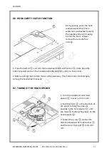
Page 17: ...ton pressed and turn the handwheel backward CW until you hear a click 2 Before running the machine motor in the usual way check the proper functioning by turning the handwheel manually D7 TIMING OF THE HOOK OPENER 1 Turn the handwheel until hook opener moves to the far right 2 Push the hook in the direction of the arrow to bring it as close as possible to the hook opener until the nose touches the...

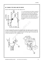
Page 18: ...r If not loosen the two screws of the small gear and rotate the hook to bring its tip to the center of the needle We call this position the machine at the set point of 2 3 mm 2 Adjust the height of the needle bar to the point when the machine is at the set point of 2 3 mm the hook tip is about 0 5 mm above the upper edge of the needle eye Loosen the needle bar screw and adjust the distance between...

Page 19: ...e gear screws Adjust the distance to 0 05 0 1 mm Then tighten all screws 4 Adjust the guard plate of the hook by bending it so that the distance between the plate and the needle is 0 1 0 2 mm The guard plate is intended to prevent contact of the needle with the hook tip if the needle bends Adjust the distance when changing the needle size w w w g a r u d a n c z ...

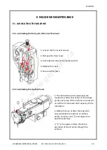
Page 20: ...ver 5 Secure with screws E1 2 Lubricating the machine head 1 The lubrication points openings are marked red Add a few drops of oil to these points every day If the machine oil could not use all the oil decrease the frequency of the lubrication 2 Before first use or after the long term stop lubricate the machine at marked points remove cover and apply oil to each felt and hose 3 C is the upper oil ...

Page 21: ...filling the oil sump 1 Place the oil filter head on the hose and put it into the oil sump as shown You can attach it using the magnet 2Add the oil until the cap is completely submerged 3 If the oil level falls below 1 3 of the head height add more oil w w w g a r u d a n c z ...

Page 22: ...t the proper amount of lubrication with a paper Place the paper close to the hook and bring the machine to maximum speed for a few seconds You should see thin lines formed by the oil on the paper Too much oil Correct amount of oil Too little oil E2 2 Adjusting the lubrication of the upper oil tank 1 If too much oil accumulates in the upper oil tank tilt the machine head and loosen the nut Turn the...

Page 23: ...ange of movement is too small 6 Reduce spring force increase the range of motion 7 Incorrect timing of the needle and hook 7 Adjust needle and hook timing see D8 2 Skipping stitches 1 Incorrect timing of the needle and hook 1 Adjust needle and hook timing see D8 2 Foot pressure too low 2 Increase the foot pressure 3 Incorrect distance between needle eye and the hook tip 3 Adjust the distance see D...

Page 24: ...eck the direction of the rotation 13 Switch off the machine and unplug it in these situations threading the needle needles hooks etc changing the needle presser foot needle plate hooks hook bobbins feeders needle guards finger guards work guides etc the machine is not in use and left unattended opening or removing the protective covers any maintenance repair inspection and adjustment of the machin...

Page 25: ... ANITA MP04800EN MP04900EN_200204 GF 1130 4412 GF 2230 4412 MH 25 G4 INSTALLATION G4 1 Connector description Control box of the AS series w w w g a r u d a n c z ...

Page 26: ...y connected to electrical outlet to ensure safe operation and to prevent machine malfunctions ATTENTION All wires must be connected separately to avoid overloading and safe operation of the machine G4 3 Connecting and settings For more information consult the installation manual for your particular engine model Power unit control box installation Make sure you have enough space on the right side o...

Page 27: ...es which can have different optional functions as thread cutting programmable back tacking automatic foot lift etc If your machine is not equipped with this option some of the features described below will not be available for your model They are shown on the display but the machine will not perform them Control panel layout Symbols of the LCD display w w w g a r u d a n c z ...

Page 28: ...0 Needle up stop position 2 Slow start 11 Free sewing mode 3 Start back tacking 12 W sewing mode 4 End back tacking 13 Segment sewing 5 Sewing segment index 14 Multi segment mode 6 Numeric display 15 Auto test 7 Foot lift after trimming 16 Clamp function 8 Foot lift after stopping 17 Four segment sewing 9 Needle down stop position w w w g a r u d a n c z ...

Page 29: ...to enter the multi segment sewing mode LCD icon is on In multi segment sewing interface use or key to set max 24 segments P01 is number of segments 01 is current segment setting 16 is number of stitches in the segment 7 Four segment sewing Press this key to enter the four segment sewing mode LCD icon is on In four segment sewing interface use the or key to set number of stitches of each segment E ...

Page 30: ...nction off 13 Foot lift mode Select the presser foot stop position up or down Pressing the key repeatedly you change foot position sewing mode 14 One step multi segment sewing When the icon is lit pressing the foot control the machine performs whole preprogrammed sewing in one step 15 Lighting Turning the light on off 16 Custom functions You can preset any custom function for this key 17 Speed Inc...

Page 31: ...og náhradních dílů Spare Parts List GF 1130 4412 MH ANITA B s r o Průmyslová 2453 7 680 01 Boskovice Czech Republic tel 420 516 454 774 420 516 453 496 fax 420 516 452 751 e mail info anita cz MP04800_200204 ...

Page 32: ...d Property of Anita B s r o and protected by copyright The use of this content without written consent of Anita B s r o is prohibited Copyright Anita B s r o 2020 VERSION CREATED ON APPROVED BY MP04800_200204 04 02 2020 Ing Kamil Krátký w w w g a r u d a n c z ...

Page 33: ...ure Adjusting Upper Feed Mechanism 2 3 16 D Pressure Adjusting Upper Feed Mechanism 3 3 18 E Feed Mechanism 1 2 20 E Feed Mechanism 2 2 22 F Hook Shaft Lower Feed Mechanism 1 2 24 F Hook Shaft Lower Feed Mechanism 2 2 26 G Thread Tension Components 28 H Lower Thread Winder Mechanism Components 30 I Automatic Presser Lifting Mechanism 32 J Lubrication Components 1 2 34 J Lubrication Components 2 2 ...

Page 34: ... ANITA MP04800_200204 GF 1130 4412 MH 4 A FRAME MISCELLANEOUS COVER 1 2 w w w g a r u d a n c z ...

Page 35: ...1608 Balance cover 1 21 SS7150910TP Screw 15 64 28 L 9 1 22 21355805 Thread guide 1 23 SS5090610SP Screw 9 64 40 L 6 1 24 B1129051000 Frame thread guide upper 1 25 SS2090710TP Screw 9 64 40 L 7 2 4 26 21408554 Thread guide asm 1 27 21408505 Thread guide plate 1 28 17912106 Needle thread presser plate 1 29 B1132521000 Thread presser plate spring 1 30 SD0380551SL Hinge screw S 3 80 H 5 5 1 31 226026...

Page 36: ... ANITA MP04800_200204 GF 1130 4412 MH 6 A FRAME MISCELLANEOUS COVER 2 2 w w w g a r u d a n c z ...

Page 37: ...130 4412 MH 7 A FRAME MISCELLANEOUS COVER 2 2 Ref No Parts No Name of parts Description Qty Note 46 21349600 Bed slide left A 1 47 CQ202000000 Oil wick L 12 2 48 10201200A Rubber plug 1 49 22619100A Cap 1 w w w g a r u d a n c z ...

Page 38: ... ANITA MP04800_200204 GF 1130 4412 MH 8 B TAKE UP AND UPPER SHAFT COMPONENTS 1 2 w w w g a r u d a n c z ...

Page 39: ...2 14 SM8080812TP Screw M8x8 2 15 21339502 Upper feed cam 3 5 1 16 SS8660810TP Screw 40 L 8 2 17 21333109 Upper shaft inner metal 1 18 CQ202000000 Oil wick 0 15 m 19 21336557 Eccentric cam A asm 1 20 21336508 Eccentric cam A 1 21 SS8660810TP Screw 40 L 8 2 22 21333703 Safety clutch disc 1 23 22604904 Upper sprocket 1 24 SS6661110SP Screw 1 4 40 L 11 2 25 22604300 Timing belt 1 26 SS8150822TP Screw ...

Page 40: ... ANITA MP04800_200204 GF 1130 4412 MH 10 B TAKE UP AND UPPER SHAFT COMPONENTS 2 2 w w w g a r u d a n c z ...

Page 41: ...tch push button 1 46 RE0500000K0 E ring 1 47 B1639051000 Spring 1 48 B1313055000 Safety clutch knob sleeve 1 49 SS8150710TP Screw 15 64 28 L 7 2 51 40038700 Thrust collar asm 1 52 40038702 Thrust collar 1 53 SS8661030SP Screw 1 4 40 L 10 2 54 SB120000200 Bearing 20x42 1 55 SS7120760SP Screw 3 16 28 L 7 0 2 56 21353008 Horizontal feed cam cover 1 57 SS7110710SP Screw 11 64 40 L 7 2 58 TA0750704R0 R...

Page 42: ... ANITA MP04800_200204 GF 1130 4412 MH 12 C NEEDLE BAR ROCKING w w w g a r u d a n c z ...

Page 43: ... MC372001600 Needle SY3355 160 2 14 B1467563000 Upper feed bar guide 1 15 SS7110910TP Screw 11 64 40 L 8 5 2 16 21388400 Rocking base guide 1 17 SS7110830SP Screw 11 64 40 L 7 5 2 18 21338603 Rocking front arm 1 19 SS6091022TP Screw 2 20 21338801 Rocking front arm 1 21 SM8080812TP Screw 2 22 21338900 Rocking shaft 1 23 B1414232000 Square block 1 24 B1410771000 Stud 1 25 21339304 Rocking shaft fron...

Page 44: ... ANITA MP04800_200204 GF 1130 4412 MH 14 D PRESSURE ADJUSTING UPPER FEED MECHANISM 1 3 w w w g a r u d a n c z ...

Page 45: ...2 17 WP0501046SC Washer 5x13x1 1 18 40033029 Triangular lever asm 1 19 SS7110510SP Screw 11 64 40 L 5 1 20 10509701 Felt 1 21 NS6680320SP Nut 9 32 28 1 22 40018341 Walking bar driving link 1 23 40033030 Walking bar A 1 24 B14670530A0 Walking bar asm 1 25 B1468053000 Walking bar spring 1 26 SS6151780SP Screw 15 64 28 L 17 0 1 27 21406509 Upper feed guide plate 1 28 26225201 Roller 1 29 SS6151920SP ...

Page 46: ... ANITA MP04800_200204 GF 1130 4412 MH 16 D PRESSURE ADJUSTING UPPER FEED MECHANISM 2 3 w w w g a r u d a n c z ...

Page 47: ...rew M8 L 10 1 55 21048707 Hinge screw 1 56 SM8050602TP Screw M5 L 6 4 57 10774354 Upper and lower dial asm 1 58 RE0800000K0 E shaped snap ring 8 mm 1 59 SS8660810TP Screw 1 4 40 L 8 2 60 10715100 Vertical dial shaft bushing 1 61 10715001 Vertical adjusting cam 1 62 10715704 Vertical dial pin 1 63 B152652700G Spring 1 64 SS6110630TP Screw 11 64 40 L 6 1 65 21341607 Vertical adjusting arm 1 66 10715...

Page 48: ... ANITA MP04800_200204 GF 1130 4412 MH 18 D PRESSURE ADJUSTING UPPER FEED MECHANISM 3 3 w w w g a r u d a n c z ...

Page 49: ...H 19 D PRESSURE ADJUSTING UPPER FEED MECHANISM 3 3 Ref No Parts No Name of parts Description Qty Note 79 21339809 Upper feed dog spring hook 1 80 SS7110830SP Screw 11 64 40 L 7 5 1 81 107013766A Eccentric rod set 1 w w w g a r u d a n c z ...

Page 50: ... ANITA MP04800_200204 GF 1130 4412 MH 20 E FEED MECHANISM 1 2 w w w g a r u d a n c z ...

Page 51: ...17 22904155 Main shaft thrust collar asm 2 18 22904106 Main shaft thrust collar 1 19 SS8660610TP Screw 1 4 40 L 6 2 20 10205201 Needle bar frame rod 1 21 SD0900701TP Hinge screw D 9 H 7 1 22 NS6680320SP Nut 9 32 28 1 23 21337506 Feed adjusting base 1 24 21337704 Feed adjusting cover 2 25 SS7110910TP Screw 11 64 40 L 8 5 4 26 21337407 Square block 2 27 21337803 Feed adjusting base support 2 28 SS81...

Page 52: ... ANITA MP04800_200204 GF 1130 4412 MH 22 E FEED MECHANISM 2 2 w w w g a r u d a n c z ...

Page 53: ...l wick 0 04 m 52 SM8050502TP Screw M5x6 1 53 21336706 Feed rod A 1 54 21338207 Feed Link pin 1 55 SD1000801SH Hinge screw D 10 H 8 1 56 21336300 Backward feed lever shaft 1 57 SS6580752TP Screw 1 8 40 L 7 2 58 CS1201010SH Thrust collar asm D 12 W 10 1 59 CS1201011SH Thrust collar D 12 W 10 1 60 SS8660610TP Screw 1 4 40 L 6 2 61 RE0900000K0 E ring 9 1 62 21388004 Reverse feed control lever 1 63 SS6...

Page 54: ... ANITA MP04800_200204 GF 1130 4412 MH 24 F HOOK SHAFT LOWER FEED MECHANISM 1 2 w w w g a r u d a n c z ...

Page 55: ...sher 1 3 1 21 10112704 Thrust washer 1 8 1 23 21378500 Hook shaft upper metal 1 24 21334701 Hook shaft lower metal 1 25 10109908 Saddle installing block upper 1 26 10112407 Saddle installing block lower 1 27 SS6153040SP Screw 15 64 28 L 30 1 28 WP0850002SP Washer 8 5x18x1 6 1 29 SM6082502TP Screw M8 L 25 1 30 B1834512000A Oil adjusting screw 1 31 NS6110530SP Nut 11 64 40 2 33 B18305630A0 Vertical ...

Page 56: ... ANITA MP04800_200204 GF 1130 4412 MH 26 F HOOK SHAFT LOWER FEED MECHANISM 2 2 w w w g a r u d a n c z ...

Page 57: ...parts Description Qty Note 46 SS8660670SP Screw 1 4 40 L 6 1 1 47 SS8660530TP Screw 1 4 40 L 4 5 1 48 V1816051000 Hook driving shaft gear large 1 49 SS8660810TP Screw 1 4 40 L 8 2 50 SS8151150SP Screw 15 64 28 L 10 5 1 51 SQ1110401MZ Connecting screw 2 52 22611909 Oil pump shaft 1 w w w g a r u d a n c z ...

Page 58: ... ANITA MP04800_200204 GF 1130 4412 MH 28 G THREAD TENSION COMPONENTS w w w g a r u d a n c z ...

Page 59: ...d tension disk 4 9 22617906 Thread tension disk presser 2 10 B3129053000 Tension spring 1 11 B3120125000 Rotating stopper 2 12 B3125012000 Thread tension nut 2 13 10124204 Thread tension post A 1 14 B3214047000 Bobbin winder tension disc 2 15 D3168555H0B Tension spring No 1 1 16 11072402 Thread tension nut 1 17 21441100 Thread release plate 1 18 SS4080620TP Screw nut 1 19 SD0470281SP Hinge screw D...

Page 60: ... ANITA MP04800_200204 GF 1130 4412 MH 30 H LOWER THREAD WINDER MECHANISM COMPONENTS w w w g a r u d a n c z ...

Page 61: ...RC0560711KP Retaining ring 1 13 RE0500000K0 E ring 1 14 R0092270200 Rubber ring 1 15 SS7091410SP Screw 9 64 40 L 13 5 1 16 SS6090520SP Screw 9 64 40 L 5 0 1 17 14512503 Bobbin adjusting plate 1 18 SS6110810TP Screw 11 64 40 L 8 3 19 10704807 Bobbin friction wheel 1 20 SM8050602TP Screw M5 L 6 2 21 10502300 Thread cutter 1 22 SS6090620SP Screw 9 64 40 L 6 2 23 21355755 Lower thread guide asm 1 24 2...

Page 62: ... ANITA MP04800_200204 GF 1130 4412 MH 32 I AUTOMATIC PRESSER LIFTING MECHANISM w w w g a r u d a n c z ...

Page 63: ...w M8 L 20 4 3 21356506 Cylinder Connecting screw 1 4 NM6080001SE Nut M8 1 5 SD0720331SP Hinge screw D 7 24 H 3 3 1 6 21356605 Lever A 1 7 21356803 Lever B 1 8 SM6051002TP Screw M5x0 8 L 10 2 9 21356704A Shaft 1 10 SPL4 01 Elbow 2 11 21356308 Cylinder stay front 1 12 21356407 Cylinder stay rear 1 13 SS6151040SP Screw 15 64 28 L 10 4 14 21356704B Nut 1 w w w g a r u d a n c z ...

Page 64: ... ANITA MP04800_200204 GF 1130 4412 MH 34 J LUBRICATION COMPONENTS 1 2 w w w g a r u d a n c z ...

Page 65: ...m 16 21347208 Take up lubrication felt 1 17 SS3090610SP Screw 9 64 40 L 6 1 18 21346002 Felt 1 19 CQ202000000 Oil wick 0 2 m 20 BT0600402EA Oil tube 0 12 m 21 B3538112000 Oil return tube holder 1 22 SS4110615SP Screw 11 64 40 L 6 1 23 40051503 Arm oil tank asm 1 24 B3520586000 Oil sight window 1 25 21345608 Arm oil tank 1 26 SQ1110401MZ Connecting screw 1 27 SQ1150451MZ Connecting screw 2 28 23630...

Page 66: ... ANITA MP04800_200204 GF 1130 4412 MH 36 J LUBRICATION COMPONENTS 2 2 w w w g a r u d a n c z ...

Page 67: ... plate 1 46 SS4110815SP Screw 11 64 40 L 8 1 47 SS6111010SP Screw 11 64 40 L 9 5 2 48 23630007 Tube 0 36 m 49 23630007 Tube 0 5 m 50 021363 Oil filter head 1 51 23630007 Tube 0 22 m 52 23630007 Tube 0 5 m 53 21338306 Lubrication felt presser 1 54 SS5090610SP Mutual vertical change felt 1 55 SS5090610SP Screw 3 16 28 L 7 0 1 56 21346606 Pipe support 1 57 23630007 Tube 0 22 58 010624 Nut 11 64 40 1 ...

Page 68: ... ANITA MP04800_200204 GF 1130 4412 MH 38 K THREAD STAND COMPONENTS w w w g a r u d a n c z ...

Page 69: ...w M6 L 16 2 7 22930705 Thread guide arm joint 2 8 22931406 Spool rest rod rubber cap 1 9 22930507 Spool rest arm 2 10 22931308 Spool rest rod upper 1 11 22931307 Spool rest rod joint 1 12 SM4051408SE Screw M5 L 14 2 13 NM6050001SE Nut M5 2 14 22930309 Spool rest rod lower 1 15 22931208 Thread guide 2 16 WS0510002KN Spring washer 2 17 NM6050001SE Nut M5 2 18 NM6160511SE Nut M16x1 5 1 19 WP1612616SE...

Page 70: ... ANITA MP04800_200204 GF 1130 4412 MH 40 L AIR MECHANISM COMPONENTS w w w g a r u d a n c z ...

Page 71: ...panel 1 3 021703 Screw D 4 1 L 20 2 4 021704 Screw M6 L 10 2 5 021705 Filter regulator 1 6 SPC8 01 Nipple 1 7 SPL6 01 Nipple 1 8 WP0621016SH Flat pad 2 9 LM6 Nut 2 10 040151 Screw 3 11 022236 Electromagnetic valve asm 1 12 APU0604 L 500 Tube ø6 1 13 APU0425 L 500 Tube ø4 3 14 021658A Safety switch 1 15 SS4110815SP Screw 2 16 021726 Pipe clamp 1 w w w g a r u d a n c z ...

Reviews: