NTX54-
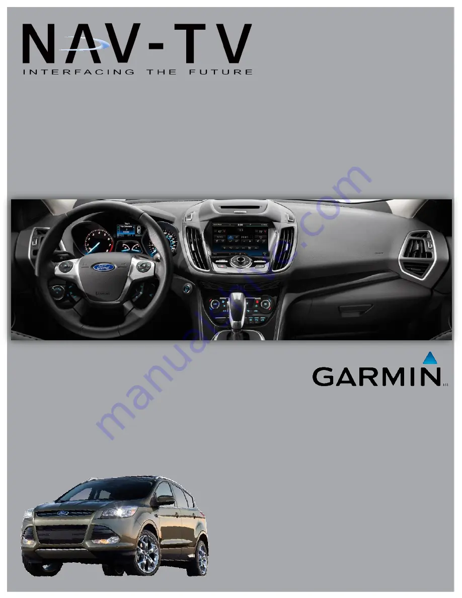
Ford
Garmin interface for Ford MyTouch Systems
BHM
8/1/13
NTV-Doc 135
Page 1: ...NTX54 Ford Garmin interface for Ford MyTouch Systems BHM 8 1 13 NTV Doc 135 ...
Page 2: ...purchase This product is intended for off road use and passenger entertainment only 2 P a g e My Ford Touch T harness LCD harness Kit Contents One modification circuit boards is included per kit Refer to the chart on the next page for qualifications Garmin GVN54 Touch Panel harness Ford Interface V2 interface circuit board V1 interface circuit board A V Aux IN harness Mode switch Aux Video OUT har...
Page 3: ... camera port NTX54 Ford Compatibility Dip Switch Settings Use the tables below to properly set the dip switches located on the side of the Ford interface When adjusting dip switches the interface power plug must be disconnected and reconnected If adding an aftermarket camera dip switch 1 must be in the UP position Year NTX 54 Ford V1 NTX54 Ford V2 2011 Edge 2011 Explorer 2013 Flex 2013 F Series 20...
Page 4: ...his product is intended for off road use and passenger entertainment only 4 P a g e Dash Disassembly Escape 1 Begin by removing the dash that surrounds the CD slot Pry up carefully with a plastic tool like shown 2 Disconnect the CD slot LED harness connected to this dash piece and set aside 3 Remove 2x 7mm screws securing the vents LCD surround 4 Gently pry the LCD surround with a plastic tool to ...
Page 5: ...bring the screen assembly to a clean soft bench to prepare for disassembly WARNING The following process is fairly involved It requires disconnecting and adding ribbon cables inside the LCD housing If any ribbon cable is not seated firmly or squarely perfectly straight it may result in improper functionality or a damaged screen Note Kits FV1 and FV2 are identical except for the screen disassembly ...
Page 6: ...nt only 6 P a g e 2 Separate the two halves of the assembly by pulling straight up after the screws have been removed Set the back half of this LCD assembly aside Note that the center connector is keyed and the halves can only be replaced in one direction 3 On the LCD panel housing mark across the brackets and the housing to make replacing later a breeze 4 On each side left and right of the LCD ho...
Page 7: ...off road use and passenger entertainment only 7 P a g e 6 Carefully separate the metal bracket from the LCD housing this will expose the touch panel ribbon cable and allow the LCD screen to be separated from the back half of the housing 7 Now separate the metal housing from the LCD panel Lifting the opposite side of the touch panel ribbon will give you easy access to remove the ribbon connectors 8...
Page 8: ...tertainment only 8 P a g e 9 Lay the back metal housing down with the circuit board facing up in the orientation shown and remove 3x Phillips head screws 10 From the NTX54 Ford kit gather the sub board with ribbons attached Fold the main bigger ribbon underneath the board like shown below You should see blue on both ends of this ribbon with this orientation 11 Gather the two short harnesses labele...
Page 9: ...2 Place the sub board in the rear LCD housing like shown This is how the sub board will be installed into the LCD housing with the OEM Ford circuit board beneath the NTX54 Ford circuit board The harnesses from step 11 will be ran through the center square and connected to their prospective connectors 13 Run the harnesses from step 11 through the center square hole like shown When connecting the wh...
Page 10: ...board needs to be palced on top Connect the wider ribbon that was tucked underneath the board from step 10 and the touch panel ribbon to the factory Ford circuit board like shown below Use the extended screws provided with the NTX54 Ford kit to secure both PCB s down to the metal chassis 15 Flip the modified LCD housing upside down and place the LCD panel just above the housing This will make reco...
Page 11: ...ting the modified screen into the vehicle it may take up to 2 minutes for the system to boot and settle NTX54 Ford Kit Installation 1 After confirmation that the Ford LCD has been modified properly the remainder of the kit must be installed Disconnect the LCD assembly and any connected harnesses Disconnect the LCD and TP harnesses from each other as shown in step 16 from the previous section 2 Gat...
Page 12: ...longer Touch Panel and LCD harnesses to the cylindrical DIN connectors from the modification at the screen These connectors are color coded labeled and keyed for your convenience Run the other end of these two cables to the interface connect to the ports labeled T P IN and LCD OUT 6 Connect the harness labeled REAR LCD to the interface only if you plan to use either the external source switch butt...
Page 13: ...ommand button on the steering wheel until the Garmin navigation displays on screen It should take about 3 seconds 2 To return to the factory Ford radio screen press and release the Home button 3 Alternatively the momentary switch provided with the NTX54 Ford kit will allow you to select the source in the order as follows Ford Garmin AUX Ford with a single press each time If you connect the DVD_IN ...