


190-01499-02
GTX 3X5 Transponder TSO Installation Manual
Rev. 4
Page 6-18
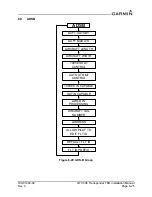
Figure 6-20 Display Pages
DISPLAY BACKLIGHT
Sets the source for the display backlight control and adjustment. Select PHOTOCELL if the lighting level
uses ambient lighting. Select LIGHTING BUS if an input from the lighting bus is used to dim the display.
MINIMUM LEVEL
Sets the minimum brightness of the display. The range is 0 to 100. The higher the number, the brighter the
minimum brightness.
KEYPAD BACKLIGHT
Sets the source for the keypad backlight control and adjustment. Select PHOTOCELL if the lighting level
uses ambient lighting. Select LIGHTING BUS if an input from the lighting bus is used to dim the keypad.
MINIMUM LEVEL
Sets the minimum brightness of the keypad. The range is 0 to 100. The higher the number, the brighter the
minimum brightness.
PHOTOCELL TRANSITION
Sets a point on the lighting bus. When the lighting bus is below this point, the GTX 3X5 uses the photocell
to adjust the display brightness. The range is 5 to 50.
PHOTOCELL SLOPE
Sets the sensitivity of the photocell input level. Adjusting the slope higher results in a greater display
brightness change for a given increase in the photocell input level. The range is 0 to 100.
OFFSET
Adjusts the lighting level up or down for any given photocell input level. This field has a range of 0 to 100.
Use the offset setting to match lighting curves with other equipment in the panel.
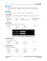
LIGHTING BUS INPUT VLTG
Sets the voltage of the lighting bus source. Selections are:
DISPLAY AND BEZEL KEY LIGHTING SLOPE
Sets the sensitivity of the display or bezel keys for any given lighting bus input level. Set the slope higher
for a brighter display for a given increase in the lighting bus input level. This field has a range of 0 to 100.
• 14 VDC
• 28 VDC
• 5 VDC
• 5 VAC