background image

• To view a perspective photo, select 

. The photo was 

taken from the location of the camera, pointed in the 

direction of the cone.

2

Select 

Photo

.

Automatic Identification System

The Automatic Identification System (AIS) enables you to 

identify and track other vessels, and alerts you to area traffic. 

When connected to an external AIS device, the chartplotter can 

show some AIS information about other vessels that are within 

range, that are equipped with a transponder, and that are 

actively transmitting AIS information.
The information reported for each vessel includes the Maritime 

Mobile Service Identity (MMSI), location, GPS speed, GPS 

heading, time that has elapsed since the last position of the 

vessel was reported, nearest approach, and time to the nearest 

approach.
Some chartplotter models also support Blue Force Tracking. 

Vessels being tracked with Blue Force Tracking are indicated on 

the chartplotter with a blue-green color.

AIS Targeting Symbols

Symbol Description

AIS vessel. The vessel is reporting AIS information. The 
direction in which the triangle is pointing indicates the 
direction in which the AIS vessel is moving.
Target is selected.

Target is activated. The target appears larger on the chart. A 
green line attached to the target indicates the heading of the 
target. The MMSI, speed, and direction of the vessel appear 
beneath the target, if the details setting has been set to Show. 
If the AIS transmission from the vessel is lost, a message 
banner appears.
Target is lost. A green X indicates that the AIS transmission 
from the vessel is lost, and the chartplotter displays a 
message banner asking whether the vessel should continue 
to be tracked. If you discontinue vessel tracking, the lost 
target symbol disappears from the chart or the 3D chart view.
Dangerous target in range. The target flashes while an alarm 
sounds and a message banner appears. After the alarm has 
been acknowledged, a solid red triangle with a red line 
attached to it indicates the location and the heading of the 
target. If the safe-zone collision alarm has been set to Off, the 
target flashes, but the audible alarm does not sound and the 
alarm banner does not appear. If the AIS transmission from 
the vessel is lost, a message banner appears.
Dangerous target is lost. A red X indicates that the AIS 
transmission from the vessel is lost, and the chartplotter 
displays a message banner asking whether the vessel should 
continue to be tracked. If you discontinue vessel tracking, the 
lost dangerous target symbol disappears from the chart or the 
3D chart view.
The location of this symbol indicates the closest point of 
approach to a dangerous target, and the numbers near the 
symbol indicate the time to the closest point of approach to 
that target.

NOTE: 

Vessels being tracked with the Blue Force Tracking 

feature are indicated with a blue-green color regardless of their 

status.

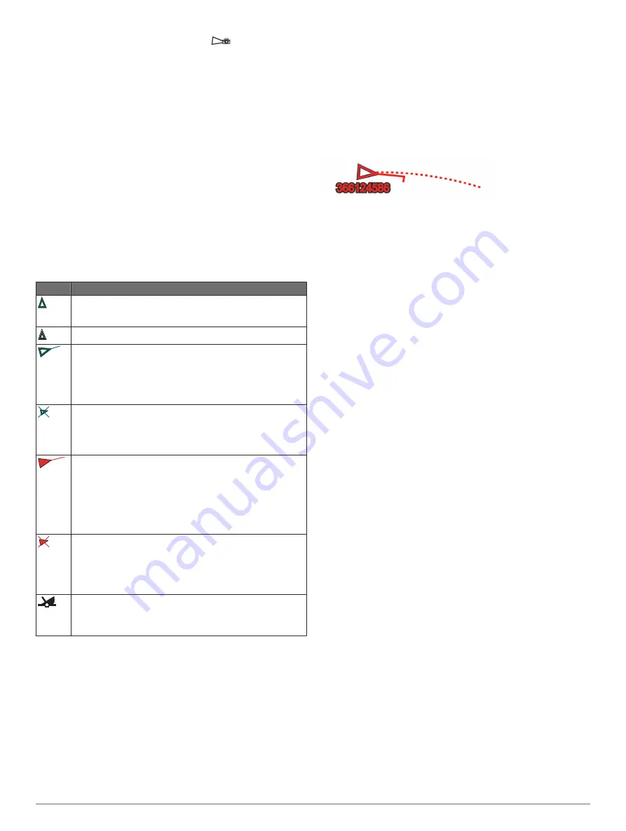
Heading and Projected Course of Activated AIS 

Targets

When heading and course over ground information are provided 

by an activated AIS target, the heading of the target appears on 

a chart as a solid line attached to the AIS target symbol. A 

heading line does not appear on a 3D chart view.
The projected course of an activated AIS target appears as a 

dashed line on a chart or a 3D chart view. The length of the 

projected course line is based on the value of the projected 

heading setting. If an activated AIS target is not transmitting 

speed information, or if the vessel is not moving, a projected 

course line does not appear. Changes in the speed, course over 

ground, or rate of turn information transmitted by the vessel can 

impact the calculation of the projected course line.
When course over ground, heading, and rate of turn information 

are provided by an activated AIS target, the projected course of 

the target is calculated based on the course over ground and the 

rate of turn information. The direction in which the target is 

turning, which is also based on the rate of turn information, is 

indicated by the direction of the barb at the end of the heading 

line. The length of the barb does not change.

When course over ground and heading information are provided 

by an activated AIS target, but rate of turn information is not 

provided, the projected course of the target is calculated based 

on the course over ground information.

Activating a Target for an AIS Vessel

1

From a chart or a 3D chart view, select an AIS vessel.

2

Select 

AIS Vessel

 > 

Activate Target

.

Viewing Information about a Targeted AIS Vessel

You can view the AIS signal status, MMSI, GPS speed, GPS 

heading, and other information that is reported about a targeted 

AIS vessel.

1

From a chart or a 3D chart view, select an AIS vessel.

2

Select 

AIS Vessel

.

Deactivating a Target for an AIS Vessel

1

From a chart or a 3D chart view, select an AIS vessel.

2

Select 

AIS Vessel

 > 

Deactivate

.

Viewing a List of AIS and MARPA Threats

1

From a chart, select 

Menu

 > 

Layers

 > 

Other Vessels

 > 

List 

Show

.

2

Select the type of threats to include in the list.

Setting the Safe-Zone Collision Alarm

Before you can set a collision alarm, you must have a 

compatible chartplotter connected to an AIS device or radar.
The safe-zone collision alarm is used only with AIS and MARPA. 

MARPA functionality works with radar. The safe zone is used for 

collision avoidance and can be customized.

1

Select 

Settings

 > 

Alarms

 > 

Collision Alarm

 > 

On

.

A message banner appears and an alarm sounds when a 

MARPA-tagged object or an AIS-activated vessel enters the 

safe-zone area around your boat. The object is also labeled 

as dangerous on the screen. When the alarm is off, the 

message banner and audible alarm are disabled, but the 

object is still labeled as dangerous on the screen.

2

Select 

Range

, and select a distance for the safe-zone radius 

around your vessel.

3

Select 

Time To

, and select a time at which the alarm will 

sound if a target is determined to intersect the safe zone.
For example, to be notified of a pending intersection 10 

minutes before it will likely occur, set Time To to 10, and the 

alarm will sound 10 minutes before the vessel intersects the 

safe zone.

4

Select 

MARPA Alarm

, and select an option for when the 

alarm sounds for MARPA-tagged objects.

AIS Distress Signals

Self-contained AIS distress signal devices transmit emergency 

position reports when activated. The chartplotter can receive 

signals from Search and Rescue Transmitters (SART), 

Emergency Position Indicating Radio Beacons (EPIRB), and 

10

Charts and 3D Chart Views

Summary of Contents for GPSMAP 8600 series

Page 1: ...GPSMAP 8400 8600SERIES Owner sManual...

Page 2: ...trademarks may not be used without the express permission of Garmin Apple is a trademark of Apple Inc registered in the U S and other countries Android is a trademark of Google Inc The BLUETOOTH word...

Page 3: ...transmission Opens the radar gain adjustment menu Opens the radar sea clutter adjustment menu Opens the radar rain clutter adjustment menu Turns on and off the radar echo trails Acquires a radar targe...

Page 4: ...2 GB microSD memory card formatted to FAT32 1 Pull down the weather cap on the back of the chartplotter 2 Insert the memory card 3 Press the card in until it clicks 4 Press the weather cap firmly shut...

Page 5: ...ol select Name Symbol Symbol and select a new symbol To change the number of functions shown and the layout of the screen select Layout and select an option To change the function of a portion of the...

Page 6: ...om a compatible screen select Menu Manage 2 Select a preset 3 Select an option To rename the preset select Rename enter a name and select Done To edit the preset select Edit and update the preset To d...

Page 7: ...ch time you want to use the ActiveCaptain feature 6 From the application store on your mobile device install and open the ActiveCaptain app 7 Bring the mobile device within 32 m 105 ft of the GPSMAP d...

Page 8: ...ptain App page 5 2 When a chart update is available and you have internet access on your mobile device select OneChart My Charts 3 Select the map to update 4 Select the area to download 5 Select Downl...

Page 9: ...Data on a Garmin Nautix Device You can connect a Garmin Nautix device to the chartplotter to view charplotter data on the Garmin Nautix device NOTE You can connect a Garmin Nautix device to multiple...

Page 10: ...ion aids including beacons lights and obstructions NOTE The Fishing chart is available with premium charts in some areas NOTE 3D chart views are available with premium charts in some areas 1 From a ch...

Page 11: ...Current Indicators page 9 An indicator for a tide station appears on the chart as a vertical bar graph with an arrow A red arrow pointing downward indicates a falling tide and a blue arrow pointing u...

Page 12: ...line does not appear on a 3D chart view The projected course of an activated AIS target appears as a dashed line on a chart or a 3D chart view The length of the projected course line is based on the...

Page 13: ...ories From a chart select Menu Layers Chart Shows and hides chart related items Chart Layer Settings page 11 My Vessel Shows and hides items relating to the boat My Vessel Layer Settings page 11 User...

Page 14: ...vated and MARPA tagged vessels Collision Alarm Sets the safe zone collision alarm Setting the Safe Zone Collision Alarm page 10 Water Layer Settings From a chart select Menu Layers Water Depth Shading...

Page 15: ...pends on the size of your memory card your sonar source and the speed of your boat as you record data You can record longer when you use a single beam sonar It is estimated that you might be able to r...

Page 16: ...e If your device has Wi Fi technology you should access the Garmin Quickdraw Community using the ActiveCaptain app Connecting to the Garmin Quickdraw Community with ActiveCaptain page 13 1 Insert the...

Page 17: ...hart in a compatible chartplotter It provides a turn by turn navigation path to the destination avoiding land and other obstacles Auto Guidance page 18 When you are using a compatible Garmin autopilot...

Page 18: ...to the location If you selected another type of SOS the call details are sent to the VHF radio You must send the call using the radio Projecting a Waypoint You can create a new waypoint by projecting...

Page 19: ...2 If necessary select Filter to see routes only or Auto Guidance paths only Editing a Saved Route You can change the name of a route or change the turns the route contains 1 Select Info User Data Rou...

Page 20: ...t Navigate To Auto Guidance 3 Review the path indicated by the magenta line 4 Select Start Navigation 5 Follow the magenta line steering to avoid land shallow water and other obstacles NOTE When using...

Page 21: ...position the Auto Guidance line unless the destination selected requires navigation through a narrow waterway 8 Select an option If the placement of the Auto Guidance line is satisfactory select Menu...

Page 22: ...create boundary areas lines and circles using the map You can also convert saved tracks and routes into boundary lines You can create a boundary area using waypoints by creating a route from the wayp...

Page 23: ...Swap Port Starbd Using the Starting Line Guidance You can use the starting line guidance feature to help get you cross the start line at the optimal speed during a sailing race 1 Mark the starting li...

Page 24: ...select Menu Autopilot Setup Wind Hold Type 2 Select Apparent or True Engaging Wind Hold Before you can enable the wind hold type you must connect a NMEA 2000 or NMEA 0183 wind sensor to the autopilot...

Page 25: ...vailable a full screen view a split screen view that combines two or more views a split zoom view and a split frequency view that displays two different frequencies You can customize the settings for...

Page 26: ...n and measure from the current location of the pin select Set Reference Panoptix Sonar Views NOTE Not all models support Panoptix transducers To receive Panoptix sonar you need a compatible chartplott...

Page 27: ...are moving and shows the entire water column in 3D from the bottom to the top of the water This view is used for finding fish Color legend Boat Range Bottom Structure Fish FrontV Sonar View The Panopt...

Page 28: ...nd transducers are mounted on your boat For example from a transducer with Garmin ClearV mounted at the back of the boat you can view the sonar data using the GPSMAP 8417 mounted at the front of your...

Page 29: ...ect Zoom In or Zoom Out to increase or decrease the magnification of the magnified area To set the depth and zoom automatically select Set Zoom Auto To cancel the zoom select No Zoom Setting the Scrol...

Page 30: ...e lowest resolution but is the least susceptible to noise It is not recommended to set echo stretch to low and filter width to high Overlay Data Sets the data shown on the sonar screen Sonar Alarms NO...

Page 31: ...might be prohibited from using frequencies between 50 to 80 khz with in mile of an orca whale pod It is your responsibility to use the device in compliance with all applicable laws and ordinances Sel...

Page 32: ...is available only with Panoptix FrontV transducers Sonar Setup Adjusts the setup of the transducer and the appearance of the sonar returns Edit Overlays Adjusts the data shown on the screen Customizin...

Page 33: ...tores the sonar settings to the factory default values Setting the Bow Offset For forward view Panoptix transducers you can enter a bow offset to compensate the forward distance readings for the trans...

Page 34: ...structions 2 Turn on the chartplotter If necessary the radar warms up and a countdown alerts you when the radar is ready 3 Select Radar 4 Select a radar mode A countdown message appears while the rada...

Page 35: ...the guard zone 5 Select Done MARPA Mini automatic radar plotting aid MARPA enables you to identify and track targets and is primarily used for collision avoidance To use MARPA you assign a MARPA tag...

Page 36: ...n Echo Trails The echo trails feature enables you to track the movement of vessels on the radar display As a vessel moves you can see a faint trail of the vessel s wake You can change the length of ti...

Page 37: ...tter and targets A higher sea clutter setting reduces the appearance of clutter caused by nearby waves but it can also reduce or eliminate the appearance of nearby targets NOTE Depending upon the rada...

Page 38: ...sates for the physical location of the radar scanner on a boat if the radar scanner does not align with the bow stern axis Measuring the Potential Front of Boat Offset The front of boat offset compens...

Page 39: ...ot display any data Autopilot Overlay Bar Actual heading Intended heading heading the autopilot is steering toward Actual heading when in standby mode Intended heading when engaged Engaging the Autopi...

Page 40: ...cancel a pattern using step steering mode Select Standby Enabling the Autopilot Controls on a Garmin Watch You can control the Garmin autopilot with a compatible Garmin watch Go to www garmin com for...

Page 41: ...r screen prompting you to activate navigation to the man overboard location disappears Man Overboard and SOS Distress Calls Initiated from the Chartplotter When your chartplotter is connected to a Gar...

Page 42: ...how the gauges pages are displayed and the data in each gauge 1 Open a gauge page 2 Select Menu Edit Gauge Pages 3 Select an option To change the data shown in a gauge select the gauge To change the...

Page 43: ...op the engine when this alert is on If you do you may not be able to restart the engine Water in the fuel Water has collected in the fuel filter fuel separator Stop the engine immediately and consult...

Page 44: ...can configure the sailing wind gauge to show true or apparent wind speed and angle 1 From the wind gauge select Menu Sailing Wind Gauge 2 Select an option To show true or apparent wind angle select N...

Page 45: ...neHelm A V Gauges InReach Start Pairing The chartplotter begins searching for and connecting to the inReach device This can take up to 60 seconds The inReach and chartplotter connect automatically whe...

Page 46: ...ts one song Searches for stations or skips songs Shuffles Selecting the Media Device and Source You can select the media source connected to the stereo When you have multiple stereo or media devices c...

Page 47: ...FM stations as presets for easy access You can save your favorite SiriusXM channels if you are connected to an optional SiriusXM tuner and antenna You can save your favorite DAB stations if you are co...

Page 48: ...can select the categories of channels that appear in the channel guide Select an option If the media device is a FUSION Link capable stereo select Media Browse Channel If the media device is a GXM ant...

Page 49: ...tervals When the Garmin receiver is turned on or when a different weather feature is selected the receiver must receive new data before it can be shown You might experience a delay before weather data...

Page 50: ...s for an area appear as variations in color Different colors indicate different wave heights as shown in the legend The wave period indicates the time in seconds between successive waves Wave period l...

Page 51: ...or to the Garmin Marine Network as well as supported network IP based video cameras encoders and thermal cameras Protected HDMI content HDCP cannot be shared across the Garmin Marine Network Select O...

Page 52: ...ut use the zoom button To pan or tilt the camera use the compass rose TIP Hold within the compass rose to continue to move the camera in the desired direction Controlling a Video Camera Using Gestures...

Page 53: ...ore than one VIRB action camera connected use the arrows to select a different action camera to control To view stored videos or images select To pan and tilt the VIRB 360 drag your finger on the scre...

Page 54: ...yer stick You must make all cable connections in a dry environment Item Description GPSMAP 8400 8600 Series chartplotter Display with an HDMI In port such as a computer or television Item Description...

Page 55: ...stead of grouping it with other displays to make a station GRID Pairing Allows you to pair a GRID remote input device with this station Display Order Sets the order of the displays which is important...

Page 56: ...ine using one or more familiar destinations that require navigation through a narrow waterway 1 Dock your vessel or drop the anchor 2 Select Settings Preferences Navigation Auto Guidance Shoreline Dis...

Page 57: ...alarm to sound when you are off course by a specified distance Setting the Anchor Drag Alarm You can set an alarm to sound if you have moved more than an allowable distance This is very useful when an...

Page 58: ...above the end of the keel measure the distance from the transducer location to the keel of the boat Enter this value as a positive number If the transducer is installed at the bottom of the keel and...

Page 59: ...ng Service Points Vessel Icon Cannot be synced between all models Restoring the Original Chartplotter Factory Settings NOTE This affects all devices on the network 1 Select Settings System System Info...

Page 60: ...download is complete eject the card from the computer 9 Insert the memory card into the card slot Memory Cards page 2 10On the chartplotter select Settings System System Information Update Built In Ma...

Page 61: ...emory card Loading the New Software on a Memory Card page 59 1 Turn on the chartplotter 2 After the home screen appears insert the memory card into the card slot NOTE In order for the software update...

Page 62: ...ettings Communications Marine Network 2 Select the GRID device Cleaning the Screen NOTICE Cleaners containing ammonia will harm the anti reflective coating The device is coated with a special anti ref...

Page 63: ...k the waypoint Position format is the way in which the GPS receiver s position appears on the screen This is commonly displayed as latitude longitude in degrees and minutes with options for degrees mi...

Page 64: ...ent draw at 24 Vdc 1 8 A Max current draw 4 9 A Device Specification Measurement Wireless frequency and protocols Wi Fi and ANT technologies 2 4 GHz 9 87 dBm nominal Memory card External card reader r...

Page 65: ...eport part B PGN Description 130313 Humidity 130314 Actual pressure 130316 Temperature Extended range 130576 Trim tab status 130577 Direction data NMEA 0183 Information Transmit Sentence Description G...

Page 66: ...ature 1 65263 Engine fluid level or pressure 1 65270 Inlet or exhaust conditions 1 65271 Vehicle electrical power 65279 Water in fuel indicator 65272 Transmission fluids 1 65248 Vehicle distance 65266...

Page 67: ......

Page 68: ...support garmin com December 2018 190 01978 00_0H...

Reviews: