background image

190-01561-00 


GIA 6300 Installation Manual 

Draft1 


Page 5 


Each discrete output is capable of sourcing 20 mA in the active state when configured as active high.  Six 
discrete outputs (3 per main board) can be used as super flag outputs capable of providing up to 0.5 
Amps of current. Active low states are capable of sinking up to 0.5 Amps.   

All of the discrete outputs have a default state of inactive implemented during and after a reset.  This is 
specifically targeted at those outputs supporting auto pilot functionality, ensuring that those outputs 
reset when the microprocessor resets. 

Each discrete input provides 1mA of wetting current when connected to ground. 

Both the Audio and Main board are capable of reading the state of 10 of the discrete inputs, and these 
pins should be reserved as practical.  This provides a low latency input path to the audio panel to allow 
for current and future functionality where delay is undesirable.  These functions include 3D Audio, 

oxygen mask selection, key’ed ICS, and additional ASR Push

-to-Command inputs. 

5.1.2


Configurable ARINC-717/708 Interface 

The GIA 6300 can support any combination of 2 ARINC-717 transceivers and 2 ARINC-708 receivers.  The 
GIA 6300 has an ARINC-708 receiver to support interfacing to a 3rd party radar.  The GIA 6300 also 
supports an ARINC-717 transceiver to add support for connecting to a 3rd party Flight Data Recorder.  
These interfaces are combined such that they can be configured between ARINC-717 and ARINC-708.   

5.1.3


Ethernet 

The GIA 6300 has a total of 4 Ethernet interfaces.  The 4 Ethernet interfaces are divided equally between 
the two processors on the main boards, each interface can be used to support redundant connections to 
the rest of the system from each processor.  Each processor can have two high speed communication 
paths independent of the 2nd processor. 

These Ethernet interfaces are all capable of up to 100 Mbps of bandwidth, but it is not available in flight. 

5.1.4


RS-485/422 

The GIA 6300 has a total of 14 RS-485 transceivers.  Any two of these transceivers can be paired 
together to make one RS-422 interface allowing up to 7 RS-422 interfaces.  The RS-485/422 interfaces 
are capable of a maximum baud rate of 921.6 kbps. 

5.2


VHF COM Interfaces 

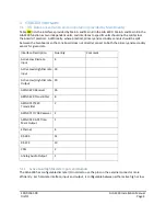
Interface Description 

Quantity 

Comment 

Analog Audio Output 


Analog Audio Input 


Active Low Discrete Inputs 


Active Low Discrete Outputs 


Active Low Discrete 
Input/Output 


Summary of Contents for GIA 6300

Page 1: ...ow High Discrete Inputs and Outputs 4 5 1 2 Configurable ARINC 717 708 Interface 5 5 1 3 Ethernet 5 5 1 4 RS 485 422 5 5 2 VHF COM Interfaces 5 5 2 1 Key Event Out 6 5 2 2 RX Squelch Break 6 5 2 3 Emergency COM Operation 6 5 3 NAV 6 5 4 Audio Panel 6 5 4 1 Transceiver Interfaces 7 5 4 2 Receiver and Alert Inputs 7 5 4 3 Headset Outputs and Microphone Inputs 7 5 4 4 AES3 Interface 7 5 4 5 Discrete ...

Page 2: ...AS receiver Audio Selection and Marker Beacon Receiver Other functions such as AFCS Flight Director have significant portions of their processing executed by the GIA 6300 The GIA 6300 is designed as though the functions are spread out across a federated system This provides independence and redundancy between the functions 2 Physical Characteristics The GIA 6300 is 7 4 wide x 5 86 high with the mo...

Page 3: ... the transceiver and the antenna The VSWR meter should be inserted as close to the transceiver as possible Any problem with the antenna installation is most likely seen as high reflected power A VSWR of 3 1 may result in up to a 50 loss in transmit power VSWR at the low mid and high end of the tuning range should be less than 3 1 for best performance VSWR should be less than 2 1 A high VSWR decrea...

Page 4: ...that one board does not directly connect to both the primary and secondary sensor for given data Interface Description Quantity Comment Active Low Discrete Input 4 Active Low High Discrete Input 30 Active Low High Discrete Output 20 ARINC 429 Receiver 26 ARINC 429 Transmitter 8 ARINC 717 429 Transmitter 2 ARINC 717 708 Receiver 2 ARINC 743 GPS Time Mark Output 1 Ethernet 4 RS 485 14 RS 232 10 CAN ...

Page 5: ...support any combination of 2 ARINC 717 transceivers and 2 ARINC 708 receivers The GIA 6300 has an ARINC 708 receiver to support interfacing to a 3rd party radar The GIA 6300 also supports an ARINC 717 transceiver to add support for connecting to a 3rd party Flight Data Recorder These interfaces are combined such that they can be configured between ARINC 717 and ARINC 708 5 1 3 Ethernet The GIA 630...

Page 6: ...rs in a CSMA environment This pin functions as both the input and output signal for a single signal between all of the digital radios in the system the two GIA 6300s and the GDR 66 5 2 3 Emergency COM Operation The Emergency COM Operation active low discrete input tunes the transceiver to the emergency frequency 121 500 MHz when active 5 3 NAV Interface Description Quantity Comment Analog Audio Ou...

Page 7: ... and 4 or 8 passenger headset locations per unit This is facilitated with 2 headset microphone crew locations and a two passenger headset outputs with 4 microphone locations and the 4 configurable Transceiver Microphone inputs The Pilot Headset and Microphone interface has a hardware failsafe connection to the integrated VHF COM When in hardware failsafe the Pilot microphone input will be hardwire...

Page 8: ...picted in C of Figure XXX the secondary AES3 interfaces will be configured to run in the low fidelity mode and the GIA s will be connected in a loop Each GIA 6300 only provides the audio sourced by its specific inputs 5 4 5 Discrete Inputs and Outputs The Audio board provides 6 discrete active low inputs and 7 discrete active low outputs The 7 outputs are for providing Push To Talk keys to the ext...

Page 9: ...e GIA 6300 is only intended for use in 28V systems but will be required to remain online down to 10 VDC for 60 seconds during engine start conditions The power supplies will be designed to allow the units to remain fully functional with minimal exceptions The Main A Main B Audio NAV and COM boards will have 200 ms of backup power provided by independent banks of capacitors Some loads and circuitry...

Page 10: ...as two independent units allowing for separation and redundancy in each GIA Both GIA 1 and GIA 2 are connected to the sensors but in each GIA Main A and Main B can be connected to a different set of sensors i e Main A is connected to all primary sensors and Main B is connected to all redundant sensors Data is shared between the two main boards through the inter processor communication The COM Digi...

Page 11: ...n controllers and GDU displays Most foreseeable systems are expected to be a subset The GIA 6300 implements 4 Ethernet interfaces between the two Main boards Main A and Main B have independent processors each with a separate HSDB address Passing between the two processors will be considered an additional HSDB hop GDU GDU GIA Main A GIA Main B GIA Main A GIA Main B GTC GTC GSD GSD GDU GDU GSD GTS G...

Page 12: ...feet from any DME antennas three feet from any GPS antennas and as far as practical from the VHF NAV and ELT antennas Some ELTs have exhibited re radiation problems generating harmonics which may interfere with other signals In addition the COM antenna must have at least 16 dB of isolation from other COM antennas to prevent damage to the GIA6300 COM receiver For COM antennas mounted on the same si...

Page 13: ...Description Aviation band VHF transceiver with 25 and 8 33 kHz channel spacing Antenna Characteristics Broad band 50 ohms vertically polarized Rated Power 20 Watts typical 16 Watts minimum Emission Type Voice 6K00A3E 25 kHz Channel Spacing Mode 5K60A3E 8 33 kHz Channel Spacing Mode Emission Type Data 13K0A2D VDL Mode A ACARS 14K0G1D VDL Mode 2 Frequency of Operation VDL Mode A and Mode 2 118 000 1...

Page 14: ...x appareils radio exempts de licence L exploitation est autorisée aux deux conditions suivantes 1 l appareil ne doit pas produire de brouillage et 2 l utilisateur de l appareil doit accepter tout brouillage radioélectrique subi même si le brouillage est susceptible d en compromettre le fonctionnement 3 Canadian installations are required to meet Industry Canada specifications for maximum radiation...

Reviews: