background image

190-01717-B1

G500/G600 TXi Part 23 AML STC Maintenance Manual

Rev. 1

Page 5-9

NOTE

(QVXUHWKHFXUUHQWFRQILJXUDWLRQLVVDYHGWRDQ6'FDUGLQDFFRUGDQFHZLWKWKHLQVWUXFWLRQV

FRQWDLQHGLQ6HFWLRQ

1. If multiple GDU 1060/700 displays are installed in the system, choose one GDU to act as the new 

master GDU.

2. Power on all LRUs in the G500/G600 TXi system with all GDUs in configuration mode.
3. From the home screen on each GDU navigate to 

GDU Type

.

4. Configure all GDU ID’s, locations, and unit configurations to match the recorded configuration 

settings in the configuration log printout.

5. Ensure that 

Master

 is selected on the GDU that has been chosen to act as the master configuration 

module.

6. At this point the G500/G600 TXi system will have a new system ID. System features will need to 

be unlocked and the system databases will need to be re-installed. The System ID must be updated 
on Flygarmin.com and then new databases can be downloaded. 

7. Insert the feature unlock card in the bottom or right slot of any GDU in the system
8. Navigate to 

Home 


System Management 

 Feature Enablement

 and enable system features.

9. Insert the SD card with the saved aircraft configuration file in the Top or left slot of any GDU in 

the system.

10. Navigate to 

Home 


SD Load

11. Select the aircraft configuration file you wish to load.
12. Select the GDU to configure, and the desired configuration settings to load.
13. Select 

SD Load.

14. Follow on screen commands.
15. Perform the Configuration Ground check in Section 5.15.1.
5.1.6

Re-installation

To replace the GDU 1060/700 perform the following procedure:

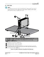
1. If equipped with an integrated ADAHRS, align the ADC module with the back of the GDU as 

shown in Figure 5-3 above and gently press the module into place.

2. Tighten the four(4) thumb screws that secure the ADC module to the back of the GDU to 10 ± 1 

LBF-IN.

3. Connect the four(4) wiring connectors and any installed antenna wires to the back of the GDU and 

tighten the retaining screws.

4. Place the GDU in the instrument panel cutout.
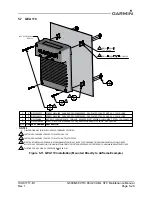
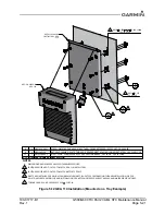
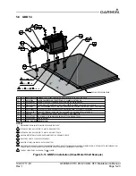
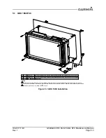
5. Install the four screws (item 1) as shown in Figure 5-1 and Figure 5-2 and tighten to 8 ± 1 LBF-IN.
6. Perform the configuration mode ground check in Section 5.15.1

Summary of Contents for G600

Page 1: ...ntenance Manual Contains Instructions for Continued Airworthiness for STC SA02571SE Aircraft make model registration number and serial number along with the applicable STC configuration information mu...

Page 2: ...oneywell International Inc 2017 SiriusXM Radio Inc Sirius XM and all related marks and logos are trademarks of SiriusXM Radio Inc All other marks and logos are property of their respective owners All...

Page 3: ...following license The free distribution and use of this software in both source and binary form is allowed with or without changes provided Distributions of this source code include the above copyrigh...

Page 4: ...le by Garmin in connection with this Agreement c Licensed Software means the software in binary executable form that is embedded in the Devices and or made available for use on the Devices via a softw...

Page 5: ...ich the export re export or distribution of such Licensed Software or Documentation is prohibited by applicable law b Protection of Software and Documentation Licensee shall use its best efforts to pr...

Page 6: ...NG TO THE CONTRARY HEREIN TO THE MAXIMUM EXTENT PERMITTED BY APPLICABLE LAW UNDER NO CIRCUMSTANCES AND REGARDLESS OF THE NATURE OF ANY CLAIM SHALL GARMIN BE LIABLE TO LICENSEE FOR AN AMOUNT IN EXCESS...

Page 7: ...overnment as a terrorist supporting country and ii you are not listed on any U S Government list of prohibited or restricted parties g Injunctive Relief The Parties acknowledge and agree that irrepara...

Page 8: ...with respect to such subject matter l Interpretation In this Agreement a headings are for convenience only and do not affect the interpretation of this Agreement b the singular includes the plural and...

Page 9: ...quipment or death CAUTION To avoid damage to the GDU 700 1060 take precautions to prevent Electrostatic Discharge ESD when handling the unit connectors and associated wiring ESD damage can be prevente...

Page 10: ...aul Period 3 6 3 8 Special Inspection Requirements 3 6 3 9 Application of Protective Treatments 3 6 3 10 Data Relative to Structural Fasteners 3 7 3 11 Additional Instructions 3 7 4 TROUBLESHOOTING 4...

Page 11: ...1 Page x TABLE OF CONTENTS CONTINUED A 5 Wire Routing Twin Engine A 5 A 6 Saved Configuration File A 6 A 7 Print Configuration Log A 6 A 8 GDU 1060 EIS Gauge Layout Template A 7 A 9 GDU 700P EIS Gaug...

Page 12: ...connectors numbering scheme for female male contacts 4 2 Figure 4 2 GDU 700P Connectors 4 3 Figure 4 3 GCU 485 Connector 4 7 Figure 4 4 View of J721 Connector looking at GDC 72 4 8 Figure 4 5 View of...

Page 13: ...Example 5 21 Figure 5 13 GBB 54 Installation Sheet Metal Shelf Example 5 23 Figure 5 14 GBB 54 Battery Cell Replacement 5 25 Figure 5 15 GMU 44 Installation Universal Mount Example 5 27 Figure 5 16 GT...

Page 14: ...Maintenance 3 2 Table 3 2 Electrical bonding requirements 3 5 Table 4 1 G500 G600 TXi Failures 4 1 Table 5 1 Pressure Sensor Equipment List 5 34 Table 5 2 LRU Status Indicators 5 42 Table 5 3 Airspee...

Page 15: ...TXi System equipment installed by this STC Section 2 2 LRU Description Control and Operation Provides basic control and operation information specifically tailored to maintenance practices Section 3...

Page 16: ...yms 1 7 1 Terminology Except where specifically noted references made to the GDU 1060 700 will apply to the GDU 1060 GDU 700P and GDU 700L equally Except where specifically noted references made to th...

Page 17: ...DME Distance Measuring Equipment RVSM Reduced Vertical Separation Minimum EGT Exhaust Gas Temperature SBAS Satellite Based Augmentation System EIS Engine Indicating System SD Secure Digital ES Extend...

Page 18: ...up Battery 2 13 2 2 13 GEA 110 Engine Interface 2 14 2 2 14 GAD 43 43e Adapter 2 15 2 2 15 EIS Components 2 16 2 1 System Overview The G500 G600 TXi installation can provide PFD MFD and EIS functions...

Page 19: ...EIS can display engine and airframe operating parameters on the GDU The EIS gauges include optional gauges and those required by the aircraft POH and manufacturer This manual only provides information...

Page 20: ...ure 2 1 Entering the configuration mode on the GDU 2 1 5 SD Card Location Options The GDU 1060 700 has two SD card slots that can be used for various tasks The following list describes what tasks can...

Page 21: ...SD card into the Top Left slot of any GDU 1060 700 in the system 2 Power on all GDUs in the G500 G600 TXi system in configuration mode 3 Ensure you have set the GDU ID s SYS ID Source and feature enab...

Page 22: ...as a PFD MFD or EIS display The GDU 700P is available with or without an integrated ADAHRS The GDU 700P requires a compatible GPS SBAS navigator for MFD and PFD functionality Figure 2 2 GDU 700P MFD P...

Page 23: ...display to automatically adjust the display back lighting in reference to ambient light conditions Top Card Slot A Card slot in the display that accepts standard SD cards See Section 2 1 5 for more in...

Page 24: ...lay layout Pressing and holding the button for 5 seconds will power off the display with no further prompt Photocell The photocell may be configured to be used by the display to automatically adjust t...

Page 25: ...playing PFD and MFD data with optional EIS display The GDU 1060 may be optionally equipped with an integrated ADAHRS or must be interfaced to an external ADC AHRS LRU Shown below is a combined PFD MFD...

Page 26: ...ns Top Card Slot A Card slot in the display that accepts standard SD cards See Section 2 1 5 for more information on SD card options Bottom Card Slot A Card slot in the display that accepts standard S...

Page 27: ...ntenna 2 2 6 Integrated ADAHRS Unit The GDU 1060 700P has an optional integrated ADAHRS unit that provides flight altitude vertical speed airspeed attitude OAT and heading data for flight instrumentat...

Page 28: ...ion is used for maintenance and configuration information The GSU 75B is configured through the GDU 1060 700P using a feature unlock card that contains airframe specific air data corrections suitable...

Page 29: ...m The GDC 72 provides data to the G500 G600 TXi using ARINC 429 digital interfaces as well as RS 232 for maintenance and configuration information Figure 2 12 GDC 72 ADC Unit 2 2 10 GMU 44 Magnetomete...

Page 30: ...TP 59 is mounted externally on the aircraft usually near or inside air inlet ducts the underside of wing access panels or on the empennage below the horizontal stabilizer Figure 2 14 GTP 59 Outside Ai...

Page 31: ...ule used for gathering sensor input parameters from the engine and processing the signals for the G500 G600 TXi system The GEA 110 can be mounted to the back assembly of the GDU 1060 or it can be remo...

Page 32: ...0 mV degree sec OR The GAD 43 43e can provide an analog baro correction output like the Honeywell KEA 130 130A and KEA 346 P N 006 0362 0008 through 0011 only encoding altimeters With the GDU 1060 700...

Page 33: ...nstalled within 8 inches of the center of the pilots field of view Figure 2 18 Engine Annunciator 2 2 15 2 Carburetor Temperature Probe The carburetor temperature probe is a Type K thermocouple Chrome...

Page 34: ...ors are small sensors that are supplied with a compatible plug Depending on the installation these sensors may be used to measure oil fuel and manifold pressure Figure 2 22 Brass Pressure Sensor 2 2 1...

Page 35: ......

Page 36: ...DC and standby instrument checkout procedures and maintenance 3 3 Maintenance Intervals Table 3 1 Periodic Maintenance Item Description Procedure Interval G500 G600 TXi System Visual Inspection All in...

Page 37: ...The number of hours the fan has been operating can be viewed using the following procedure 1 Power on the GDU 1060 700 in configuration mode per the instructions in Section 2 1 4 2 Navigate to Diagno...

Page 38: ...side to the exterior of the aircraft 3 4 1 Aluminum Foil Tape non metallic aircraft only Any aluminum foil tape used in the G500 G600 TXi installation for grounding of a GSU 75 75B GDC 72 GRS 79 GAD...

Page 39: ...st be inspected as specified in Socata Maintenance Manual Section 05 10 01 ATA Chapter 53 The air data systems must be checked within the preceding 24 months as specified in the Socata Maintenance Man...

Page 40: ...ting denting or discoloration Check P441 and J441 for melting or pin damage Check the cable overbraid for pinching melting or evidence of arcing Check the lug for evidence of arcing and verify that th...

Page 41: ...C Maintenance Manual Rev 1 Page 3 7 3 10 Data Relative to Structural Fasteners Data relative to structural fasteners such as type torque and installation requirements can be found in Section 5 of this...

Page 42: ...current configuration log to ensure that system configuration settings match those recorded in the aircraft s permanent records If the current aircraft configuration does not match the configuration...

Page 43: ...7 Open the htm file with the name that you entered in step 4 8 The file should open in your computer internet browser and can be printed using your selected internet browser print function in most cas...

Page 44: ...onnectors and pin functions GDU 700 and GDU 1060 displays have seven connectors J1 P1 26 pin female contact HD D sub J2 P2 44 pin female contact HD D sub J3 P3 62 pin female contact HD D sub J4 P4 78...

Page 45: ...Pin Function I O 1 RS 485 1A I O 23 ETHERNET OUT 4A OUT 2 RS 485 1B I O 24 GND 3 LIGHTING BUS HI IN 25 RESERVED 4 LIGHTING BUS LO IN 26 MAGNETOMETER GND 5 OAT POWER OUT 27 RS 232 IN 2 IN 6 OAT PROBE...

Page 46: ...VERTICAL FLAG OUT OUT 43 DISC OUT 1 LO OUT 13 VERTICAL UP OUT OUT 44 RS 485 2A I O 14 VERTICAL DOWN OUT OUT 45 RS 485 2B I O 15 A P COURSE ERROR LO 46 RS 485 3A I O 16 A P COURSE ERROR HI OUT 47 RS 4...

Page 47: ...17 RS 232 OUT 6 OUT 56 ARINC 429 OUT 4A OUT 18 RS 232 GND 5 57 ADF X COS IN IN 19 RS 232 IN 5 IN 58 ADF Y SIN IN IN 20 RS 232 OUT 5 OUT 59 ADF DC REF IN IN 21 ARINC 429 IN 1B IN 60 DISC OUT LOW 13 OU...

Page 48: ...le contact HD D Sub Figure 4 3 GCU 485 Connector J4851 P4851 Connector Pin Function I O 1 RS 232 OUT 1 OUT 2 RS 232 IN 1 IN 3 RS 232 OUT 2 OUT 4 RS 232 IN 2 IN 5 POWER GROUND 6 SIGNAL GROUND 7 AIRCRAF...

Page 49: ...NFIG MODULE POWER OUT 15 SIGNAL GROUND 54 CONFIG MODULE DATA I O 16 AIRCRAFT POWER 2 IN 55 CONFIG MODULE CLOCK OUT 17 RS232 OUT 2 OUT 56 DISCRETE IN 1 IN 18 RS232 IN 2 IN 57 SYS ID 2 IN 19 RESERVED 58...

Page 50: ...AML STC Maintenance Manual Rev 1 Page 4 9 Indicates active low 35 SPARE 74 CONFIG MODULE GROUND 36 AIRCRAFT GROUND 2 75 SYS ID 1 IN 37 SIGNAL GROUND 76 DISCRETE IN 3 IN 38 RESERVED 77 DISCRETE IN 4 I...

Page 51: ...WER OUT 15 SIGNAL GROUND 54 CONFIG MODULE DATA I O 16 AIRCRAFT POWER 2 IN 55 CONFIG MODULE CLOCK OUT 17 RS 232 OUT ADC 2 OUT 56 DISCRETE IN 1 IN 18 RS 232 IN ADC 2 IN 57 SYS ID 2 IN 19 RESERVED 58 RES...

Page 52: ...C Maintenance Manual Rev 1 Page 4 11 Indicates active low 35 RESERVED 74 CONFIG MODULE GROUND 36 AIRCRAFT GROUND 2 75 SYS ID 1 IN 37 RS 232 ADC 2 GROUND 76 DISCRETE IN 3 IN 38 RESERVED 77 DISCRETE IN...

Page 53: ...RCRAFT POWER 1 IN 53 CONFIG MODULE POWER OUT 15 SIGNAL GROUND 54 CONFIG MODULE DATA I O 16 AIRCRAFT POWER 2 IN 55 CONFIG MODULE CLOCK OUT 17 RESERVED 56 DISCRETE IN 1 IN 18 RESERVED 57 SYS ID 2 IN 19...

Page 54: ...ML STC Maintenance Manual Rev 1 Page 4 13 Indicates active low 35 SPARE 74 CONFIG MODULE GROUND 36 AIRCRAFT GROUND 2 75 SYS ID 1 IN 37 SIGNAL GROUND 76 DISCRETE IN 3 IN 38 RESERVED 77 DISCRETE IN 4 IN...

Page 55: ...UT 2 OUT 36 5VAC OUT HI OUT 12 WXR PITCH OUT HI 50mV deg OUT 37 115VAC REF IN LO IN 13 PITCH DC OUT OUT 38 115VAC REF IN HI IN 14 ROLL SYNCHRO OUT Y OUT 39 26VAC REF IN HI IN 15 PITCH SYNCHRO OUT Y OU...

Page 56: ...T TUNE K50 IN IN 12 RESERVED 51 DME SUPERFLAG IN IN 13 RESERVED 52 DME HOLD OUT OUT 14 RESERVED 53 ALT HOLD OUT 15 GROUND 54 GROUND 16 RESERVED 55 RESERVED 17 VS CMD OUT 56 RESERVED 18 GROUND 57 RESER...

Page 57: ...OMPOSITE 1 LO IN 3 VOR LOC COMPOSITE 2 HI IN 4 VOR LOC COMPOSITE 2 LO IN 5 GROUND 6 GLIDESLOPE 1 UP IN IN 7 GLIDESLOPE 1 DN IN IN 8 GLIDESLOPE 2 UP IN IN 9 GLIDESLOPE 2 DN IN IN 10 RESERVED 11 GROUND...

Page 58: ...contact HD D Sub Figure 4 10 GEA 110 Connectors Figure 4 11 GEA 110 J1101 P1101 Connector looking at unit Pin Function I O 1 AV PWR IN 1 IN 2 RESERVED 3 DISCRETE OUT 1 OUT 4 RS 485 2A I O 5 RS 485 1A...

Page 59: ...FUEL QUANTITY 4 GENERAL PURPOSE 6 IN 15 FUEL FLOW 1 IN 54 GND 16 FUEL FLOW 2 IN 55 SHUNT 1 IN 17 12 VDC OUT 56 SHUNT 2 IN 18 RPM IN 1 IN 57 BUS 1 IN 19 RPM IN 2 IN 58 BUS 2 IN 20 CONFIG MOD PWR OUT 5...

Page 60: ...4 19 33 FUEL QUANTITY 3 GENERAL PURPOSE 5 IN 72 FUEL QUANTITY 2 GENERAL PURPOSE 4 IN 34 GND 73 FUEL QUANTITY 4 GENERAL PURPOSE 6 IN 35 SHUNT 1 IN 74 GND 36 SHUNT 2 IN 75 SPARE 37 RPM IN 1 IN 76 5 VDC...

Page 61: ...Sub Figure 4 13 GBB 54 J541 P541 Connector Pin Function I O 1 POWER IN IN 2 POWER IN IN 3 GROUND 4 STANDBY OUT 5 GROUND 6 GROUND 7 BATTERY POWER OUT 8 BATTERY POWER OUT 9 POWER IN IN 10 GROUND 11 RS 2...

Page 62: ...ector Rather a 3 conductor shielded cable extends from the sensor for interface with a GDU or GDC unit 3 Conductor Shielded Cable Pin Function I O 1 SIGNAL GROUND 2 RS 485 OUT B Out 3 SIGNAL GROUND 4...

Page 63: ...lures and alert messages It is recommended that system troubleshooting and repair only be completed by a Garmin dealer If a specific alert or fault condition is not listed or the fault still exists af...

Page 64: ...ne or m ore G D U s in the system have a different softw are version S ervice R equired C ause C o rrective A ction B acklight calibration lost C orrective A ctio n J2 P in 39 on the G D U is grounde...

Page 65: ...is message is expected if a GDU has been replaced Internal Config module has been overwritten by harness config module Cause Corrective Action Battery unavailable power output failed Corrective Action...

Page 66: ...ive Action Service Soon Cause Corrective Action AHRS 1 2 not receiving GPS aiding The AHRS has reported that no GPS data is being received Verify the GPS source is on and has a clear view of the sky A...

Page 67: ...1 2 configuration and wiring ADC loss of communication OR No GTP 59 signal Cause Cause Corrective Action Corrective Action ADC 1 2 airspeed error correction is unavailable The alert flag has been set...

Page 68: ...S is not receiving a signal Corrective Action Ext TAW S Fail Corrective Action See external TAW S unit manual for troubleshooting instructions Ext TAW S N A Corrective Action Backup GPS is active OR N...

Page 69: ...ative C o rre ctiv e A c tio n C o rre ctiv e A c tio n T rou blesh oo t d evice fa ilure in accord an ce w ith A D S B L R U m a in ten an ce m a nu al 10 90 E S tra ffic re ceiver fa ult C o rre cti...

Page 70: ...n unit for service Corrective Action Audio Inoperative Cause Audio device failed OR Audio clip failed to play Corrective Action Cause Corrective Action ARINC 708 weather radar requires service See A70...

Page 71: ...c tio n S iriu s X M re c e iv e r in o p e ra tiv e C a u s e C o rre c tiv e A c tio n S to rm s c o p e is n o t c o n fig u re d o r o p e ra tin g p ro p e rly S to rm sco p e is re p o rtin g f...

Page 72: ...ig module is missing or has failed Corrective Action Cause Corrective Action External LRU reports service required The external LRU is reporting that service is required Return External LRU to Garmin...

Page 73: ...reference is not being provided Corrective A ction G AD reports yaw rate deviation C ause C orrective Action ARIN C 429 heading data from the AH R S has tim ed out Inspect AR IN C 429 data bus wiring...

Page 74: ...The internal G AD 43 43e configuration data does not pass C R C check G A D reports configuration integrity fault C ause C orrective A ction A n internal com ponent has faulted G A D reports unit fau...

Page 75: ...nsor config OR Interference Fuel flow indication unstable Cause Corrective Action Fuel flow requires calibration Calibrate fuel flow Limited to 15 in GDU Normal Mode More adjustment will require a dif...

Page 76: ...tallation 5 15 5 4 3 Checkout 5 15 5 5 GSU 75 GRS 79 5 16 5 5 1 Removal 5 16 5 5 2 Installation 5 17 5 5 3 Checkout 5 17 5 6 GAD 43 43e 5 18 5 6 1 Removal 5 19 5 6 2 Re Installation 5 19 5 6 3 Checkou...

Page 77: ...Xi system Refer to Section 4 for the definition of connectors and pin functions for G500 G600 TXi system LRUs Before performing any maintenance on the G500 G600 TXi system all information in Appendix...

Page 78: ...NOTES 5 9 76 5 167 3 5 0 5 1 60 5 9 7 8 7 3 35 3 5 7 21 25 1 167 7 21 25 3 5 0 67 35 3 5 7 21 25 1 167 7 21 2 5 9 76 1 6 5 6 52 7 0 66 1 5 5 0 6758 785 6 72548 81 6 5 6 1 QTY ITEM PART NUMBER DESCRIP...

Page 79: ...t configuration is saved to an SD card in accordance with the instructions contained in Section 2 1 6 2 Turn off the GDU and remove power for the GDU 1 4 2 8 3 4 NOTES 5 9 76 5 167 3 5 0 5 1 60 5 9 7...

Page 80: ...ring the fan module to the rear of the GDU and discard the o rings 3 Grasp the fan module and gently pull the module out of the GDU 4 Visually inspect the inside of the fan module receptacle on the ba...

Page 81: ...ing procedure a Power on the GDU 1060 700 in configuration mode per the instructions in Section 2 1 4 b Navigate to Diagnostics Temp Power Stats c Press Reset Fan Hours 5 1 3 Integrated ADC Module Rep...

Page 82: ...WLRQV FRQWDLQHG LQ 6HFWLRQ NOTE All item numbers in this procedure reference Figure 5 4 1 Remove the GDU in accordance with Section 5 1 1 2 Remove the backshell cover 7 from connector P2 by removing t...

Page 83: ...the G500 G600 TXi system Master configuration module requires the use of an Installer unlock card and must be performed by an authorized Garmin Dealer Physical replacement of the master configuration...

Page 84: ...om or right slot of any GDU in the system 8 Navigate to Home System Management Feature Enablement and enable system features 9 Insert the SD card with the saved aircraft configuration file in the Top...

Page 85: ...g the following procedure 1 Remove power to the GCU 485 2 Insert a 3 32 hex drive tool into the holes in the top and bottom of the front panel 3 Turn counter clockwise until the pawl latches are able...

Page 86: ...ll the GCU 485 perform the following procedure 1 Connect the electrical connector to the back of the GCU 485 2 Place the unit in the panel cutout ensuring that the pawl latches are fully retracted and...

Page 87: ...the pushbutton cap until the module can be removed from the housing 4 Insert an Aerospace Optics connector extraction tool P N 18 234 into the slots at the top and bottom of the electrical connector...

Page 88: ...lowing procedure 1 Orient the keyed electrical connector to the module and press together until locked 2 Orient the annunciator for proper viewing and gently slide the module into the housing until se...

Page 89: ...to the GDC 72 5 7 3 3 6 5 7 3 3 6 5 5 027 5 5 1 3 7 02817 5 5 7 20387 5 EKd D E KE Z E E hE Kd Zt W d E Z K Z K d dK D d Z DKd Z d E Z K Z K d dK D d EhdW d d D Z s d Z E d W Z D Z E D Z s d h dzW WZ...

Page 90: ...pawls 2 Engage mounting screw and torque screw to 15 20 LBF IN 3 Connect pitot static lines 4 Connect electrical connector 5 4 3 Checkout Perform a static and pitot system leak test in accordance with...

Page 91: ...libration of the AHRS which requires an installer unlock card 5 5 1 Removal Removal of the GSU 75 or GRS 79 can be accomplished using the following procedure 1 Remove power to the unit 2 Disconnect el...

Page 92: ...panel avionics shelf has been moved in any way the following AHRS calibration procedures must be performed as described in Section 6 of the G500 G600 TXi Part 23 AML STC Installation Manual P N 190 01...

Page 93: ...configure the new unit Figure 5 10 GAD 43 Installation Sheet Metal Shelf Example 5 7 3 3 6 5 7 3 3 6 5 37 5 EKd D E KE Z E E hE Kd Zt W d E Z K Z K d dK D d Wd Z d E Z K Z K d dK D d EhdW d d D Z s d...

Page 94: ...rforming the removal process in reverse Torque the mounting screws to the specifications provided in Figure 5 10 5 6 3 Checkout If the GAD 43 43e has been replaced perform the following procedure 1 In...

Page 95: ...Kd Zt W d E Z K Z K d dK D d d E Z K Z K d dK D d EhdW d d D Z s d Z E d W Z D Z E D Z s d h dzW WZ W Z d KE KZ E E d d KE KZ W Z D d WZ W Z d KE KZ E E d d KE K Z s d E Z t ZK d D E Z Z D dZh dhZ dK...

Page 96: ...E E hE Kd Zt W d E Z K Z K d dK D d E d dZ z d E Z K Z K d dK D d EhdW d d D Z s d Z E d W Z D Z E D Z s d h dzW WZ W Z d KE KZ E E d d KE KZ W Z D d WZ W Z d KE KZ E E d d KE K Z s d E Z t ZK d D E Z...

Page 97: ...nit is secure If the GEA 110 was replaced the sensor configurations must be loaded to the new unit using the following procedure 1 Insert saved configuration SD card in the Top or Left SD card slot of...

Page 98: ...Z Wd Z d D E h t d d dd Zz Z s d Z E d W Z D Z E D Z s d h dzW WZ W Z d KE KZ E E d d KE KZ W Z D d WZ W Z d KE KZ E E d d KE K Z s d E Z t ZK d D E Z Z D dZh dhZ dKZYh hE Z t E 47 7 0 3 57 180 5 6 5...

Page 99: ...required Refer to Figure 5 14 Removal Steps 1 Remove the four bolts 1 and four nuts 7 2 Pull battery cover 2 from housing 5 3 Discard gasket 3 4 Remove four bolts 8 that secure the battery to battery...

Page 100: ...ical connector 4 Perform the checkout in Section 5 8 4 5 8 4 Checkout 1 Perform a Configuration Mode Ground Check as described in Section 5 15 1 2 Perform the Backup Battery Check as described in Sect...

Page 101: ...211 60037 08 If original screws are reused coat screw threads with Loctite 242 blue thread locking compound Garmin PN 291 00023 02 or equivalent To re install the GMU 44 perform the following procedur...

Page 102: ...hEd D z d D d E Z K Z K d dK D d EhdW d d D Z s d Z E d W Z D Z E D Z s d h dzW WZ W Z d KE KZ E E d d KE KZ W Z D d WZ W Z d KE KZ E E d d KE K Z s d E Z t ZK d D E Z Z D dZh dhZ Z t W Zd K Dh KEE dK...

Page 103: ...ove GTP from hole 7 3 3 6 9 1 63 5 7 3 0 1 5 5 5 7 6 1 0 7 EKd D E KE Z E E hE Kd Zt W Ehd d D t Z d D E WZK d D Z W Zd K dW K d WZK D z d ZD E W E D E DhD Kh Z KtE Z h Z W KWd KE Kh Z d E KE h d Z d...

Page 104: ...is horizontal or as close to horizontal as practical given the shape of the glare shield Figure 5 17 Backup GPS Antenna Installation Non removable Installation Example 5 7 3 3 6 5 7 3 3 6 5 7 3 3 6 5...

Page 105: ...remove the GDU per Section 5 1 1 5 11 2 Installation Install the backup GPS antenna in the reverse order of the removal procedure 5 11 3 Checkout Perform the Backup GPS checkout procedure as described...

Page 106: ...es manual or practices defined in Chapter 11 Electrical Systems of advisory circular AC 43 13 1B Aircraft Inspection and Repair Sensors must be connected using hoses and fittings approved as part of a...

Page 107: ...es must remain free of contaminants during work near and around the carburetor 5 67 1 81 7 5 3257 1 5 85 725 EKd t E E d K d E KZ d Z K h t d d E K Z hZ dKZ ZZ h t Z Z Yh Z dK W d E KZ KZ E z d d DW Z...

Page 108: ...ken side of the crush washer must face the sensor flange Sensor is torqued finger tight plus turn and safety wired in accordance with practices defined in Section 7 Safetying of Chapter 7 Aircraft Har...

Page 109: ...sensors directly below fittings or components that may leak flammable fluid 3 Thread sealant or tape must be used for the NPT threads To reduce the risk of system contamination minimal amount of seal...

Page 110: ...KZ EWd W W d Z h E Ed d W Z d dtK d Z dK Z D E Z K Ed d W DW d E KZ K z d D KZ d KhW E d D dK DKhEd d E KZ 47 7 0 3 57 180 5 6 5 37 21 78 1 2 1 6 3 6 5 7 67 3 7 1 7 2 06 6 5 0 1 3 1 5266 5 66 81 1 21...

Page 111: ...d dZ KEE dKZ WK Ed KtEt Z yy WZ hZ E KZ d E Z dd E D t d hE d Z E Z Yh Z Z Z dh KEE d KE DW d E KZ K z d D dK DKhEd DW EKd dK K s Ed K E E KZ K z WZ Ed 47 7 0 3 57 180 5 6 5 37 21 78 1 2 1 6 3 6 5 7...

Page 112: ...reduce the risk of fuel system contamination minimal amount of sealant should be applied leaving at least 2 threads at the end of the fitting clear of sealant tape 3 Fitting torque must not exceed 12...

Page 113: ...the ignition switch To replace the P Lead wire remove the old section of wire and replace the entire wire and parallel resistors in accordance with the P Lead installation instructions contained in t...

Page 114: ...ibration requires the use of an Installer unlock card If it becomes necessary to re calibrate the fuel level refer to the calibration procedure contained in the G500 G600 TXi Part 23 AML STC Installat...

Page 115: ...ernal Systems Weather Radar Calibration Weather radar calibration requires the use of an Installer unlock card If it becomes necessary to re calibrate the weather radar refer to the calibration proced...

Page 116: ...m Management Software Upload 5 Select the LRUs to upload software to from the list of available LRUs NOTE Only LRUs that are configured in the system and currently online will be selectable for softwa...

Page 117: ...3 Verify if any LRU sections have a yellow warning triangle present that the configuration is valid 5 15 1 3 Capturing and Saving Screen Shots Screen shots can be captured and saved to an SD card on a...

Page 118: ...ystems can be tested at the same time or separate tests must be completed for each system 3 Using a Pitot static test set increase the airspeed until the PFD airspeed tape pointer is at the bottom of...

Page 119: ...and PFD airspeed tape are at the same airspeed value 15 Starting at the current airspeed decrease the airspeed to zero stopping at each of the airspeeds listed in Table 5 3 airspeeds above Vne should...

Page 120: ...s and at all Marking values configured per the instructions in Table 5 4 and Table 5 5 and listed in the printed configuration log 6 Verify that the ranges and markings on the standby ASI and PFD are...

Page 121: ...range If WHITE and GREEN arcs overlap set the Max value to the beginning of the WHITE GREEN arc If White and GREEN arcs do not overlap set the Max value to the top of the POH AFM or aircraft specific...

Page 122: ...nge 2 Limitations If the YELLOW arc is defined by the AFM POH or aircraft specification set to ON with Min value equal to Maximum structural speed Vno Max value should be configured to Vne or the high...

Page 123: ...the criteria in the following sections The air data tests and surface checks are required within the previous 24 months Marking Description POH AFM Section Note WHITE TRIANGLE A small white triangle m...

Page 124: ...tic system and it is not SSEC corrected 1 Connect the Pitot static tester to the aircraft left and right Pitot and static ports in accordance with Socata Maintenance Manual Section 34 11 00 2 Perform...

Page 125: ...09 to 4059 8000 120 8038 8008 to 8068 8008 to 8068 8013 to 8063 300 8219 8129 to 8249 8129 to 8249 8194 to 8244 10000 150 10059 10029 to 10089 10029 to 10089 10034 to 10084 11000 120 11042 11007 to 11...

Page 126: ...utopilot altitude hold engaged Non turbulent non gust conditions 2 Record the data specified in Table 5 7 from the primary cockpit displays every 5 minutes for a minimum flight segment of 30 minutes i...

Page 127: ...f maintaining altitude within 65 feet of the selected cruise altitude Table 5 7 Altitude Hold Check Log Aircraft S N Pilot Date En route to Time hr min Pilot Co pilot Altitude ft Airspeed kt Altitude...

Page 128: ..._______________ AIRCRAFT MAKE _________________________________________________________________ AIRCRAFT MODEL _________________________________________________________________ AIRCRAFT SERIAL _______...

Page 129: ...5 1 011 03094 ________ GSU 75 2 011 03094 ________ GRS 77 1 011 00868 ________ GRS 77 2 011 00868 ________ GRS 79 1 011 03732 ________ GRS 79 2 011 03732 ________ GMU 44 1 011 00870 ________ GMU 44 2...

Page 130: ...selage station and provide a brief description of the location Unit Station CG Description of Location GDU 1 in GDU 2 in GDU 3 in GDU 4 in GSU 75 1 in GSU 75 2 in GRS 77 1 in GRS 77 2 in GRS 79 1 in G...

Page 131: ...G500 G600 TXi Part 23 AML STC Maintenance Manual Page A 4 Wire Routing Single Engine The following diagram depicts the wire routing for the G500 G600 LRUs throughout the aircraft structure for a sing...

Page 132: ...1 G500 G600 TXi Part 23 AML STC Maintenance Manual Page A 5 Wire Routing Twin Engine The following diagram depicts the wire routing for the G500 G600 LRUs throughout the aircraft structure for a twin...

Page 133: ...B3030 00 and extract to an SD card 2 Place the recently built SD card in the top slot of the Master GDU 3 Power all GDUs in configuration mode 4 Press SD Save and enter a file name to save recommend t...

Page 134: ...G600 TXi Part 23 AML STC Maintenance Manual Rev 1 Page A 7 A 8 GDU 1060 EIS Gauge Layout Template Figure A 1 GDU 1060 EIS Gauge Template GDU 1060 Twin Engine Layout GDU 1060 Single Engine Layout E G T...

Page 135: ...TXi Part 23 AML STC Maintenance Manual Rev 1 Page A 8 A 9 GDU 700P EIS Gauge Layout Template Figure A 2 GDU 700P EIS Gauge Layout Template GDU 700P Twin Engine Layout GDU 700P Single Engine Layout E...

Page 136: ...G600 TXi Part 23 AML STC Maintenance Manual Rev 1 Page A 9 A 10GDU 700L EIS Gauge Layout Template Figure A 3 GDU 700L EIS Gauge Layout Template GDU 700L Twin Engine Layout GDU 700L Single Engine Layou...

Page 137: ......

Reviews: