2-7
190-01150-02 Rev. J
Garmin G500H Pilot’s Guide
For
ewor
d
Sec 1
System
Sec 2
PFD
Sec 3
MFD
Sec 4
Hazar
d
Avoidance
Sec 5
Additional
Featur
es
Sec 6
Annun.
& Alerts
Sec 7
Symbols
Sec 8
Glossary
Appendix A
Appendix B
Index
2.2.1 Markings
A color-coded speed range strip is located on the moving tape. The colors are
configured to match the approved markings for the installation. See the AFM/
POH.
NOTE
:
The actual colors and patterns of the airspeed tape may vary by
installation. See your AFM/POH for more details.
2.2.2
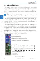
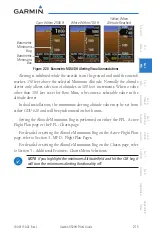
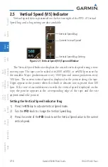
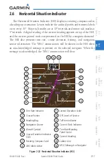
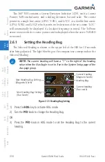
Reference Speeds
V-speeds (Glide and V
Y
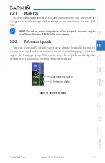
) default values are set during the installation process,
but can be changed and turned on/off from the System Setup page on the first
page of the Aux page group. When active (on), the V-speeds are displayed at
their respective locations to the right of the airspeed scale.
Glide Reference Marker
V
y
Reference Marker
Figure 2-8 Reference Speeds
Summary of Contents for G500H
Page 1: ...G500H Pilot s Guide ...
Page 365: ......

