


190-01115-01
G3X/G3X Touch Installation Manual - LRU Pinouts
Rev. AC
Page 25-36
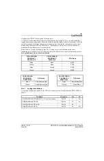
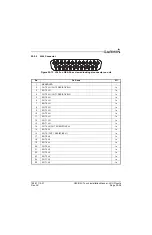
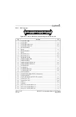
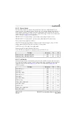
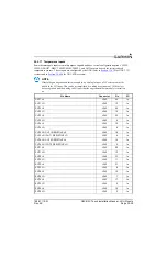
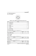
25.5.12 GP (General Purpose) Inputs
These inputs are configured by the GDU (refer to
for GDU 4XX systems) and are capable of reading any voltage up to 40 Vdc. The GEA 24 has 7
position inputs, labeled POS 1 through 7, and 7 general purpose inputs, GP 1 through 7 (to limit the length
of pin names, “GPX” is not used on all pins), each of these are paired together.
When using the GP6 and GP7 inputs for general-purpose voltage sensing, including position sensors and
user-defined analog parameters, the corresponding GP6 LO or GP7 LO pin must be connected to ground.
The GP1-GP7 inputs may also be used as additional discrete inputs. When configured as an Active Low
discrete input, the GP1-GP7 inputs require an additional pull-up resistor, as shown in
.
Potentiometer based sensors can be used by connecting the potentiometer across a +5 V supply and ground
and reading back the center tap voltage on GP1-G7/POS1-7. Some General Purpose inputs have multiple
functions.
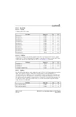
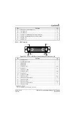
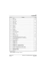
Pin Name
Connector
Pin
I/O
GP1 HI / +5V
J244
18
Out
GP1 / POS 1
J244
19
In
GP1 LO / GND
J244
20
--
GP2 HI / +5V
J244
21
Out
GP2 / POS 2
J244
22
In
GP2 LO / GND
J244
23
--
GP +5V_2
J244
24
Out
GP GND_2
J244
26
--
GP +5V_3
J244
27
Out
GP GND_3
J244
29
--
POS 3 HI / +5V
J244
11
Out
POS 3 / GP 3 / FUEL QTY 3
J244
12
In
POS 4 HI / +5V
J244
14
Out
POS 4 / GP 4 / FUEL QTY 4
J244
15
In
POS 5 HI / +5V
J244
30
Out
POS 5 / GP 5 / MISC PRESS
J244
31
In
POS 5 LO / GP 5 / GND
J244
32
--
GP +12V
J244
50
Out
POS 6 / GP 6 / TIT 1/ MISC TEMP 1 HI
J243
31
In
POS 6 / GP 6 / TIT 1/ MISC TEMP 1 LO
J243
30
In
POS 7 / GP7 / TIT 2/ MISC TEMP 2 HI
J243
29
In
POS 7 / GP 7 / TIT 2/ MISC TEMP 2 LO
J243
28
In
GP +5V
J243
26
Out
GP GND
J243
27
--


