190-01115-01
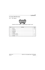
G3X/G3X Touch Installation Manual - LRU Pinouts
Rev. AC
Page 25-15
25.3.2
Aircraft Power
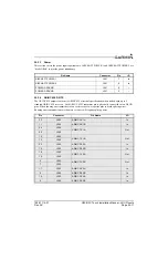
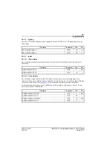
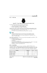
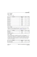
The GDU 37X can operate using power from one or both inputs (AIRCRAFT POWER 1 AND
AIRCRAFT POWER 2). The pins are internally connected using diodes to prevent current from flowing
between the two power inputs. AIRCRAFT POWER 2 is for connecting to an alternate power source, such
as on aircraft with two electrical buses.
25.3.3
Mode Selections, CDU System ID Program Pins
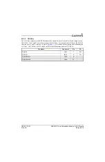
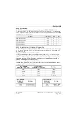
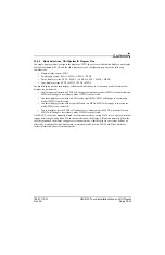
In a single-display system, configure the display as PFD1. In a two display-system, configure one display
as PFD1 and the other display as MFD. In a three-display system, one display is PFD1, one is the MFD,
and the third is PFD2.
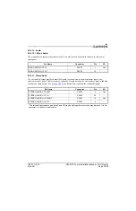
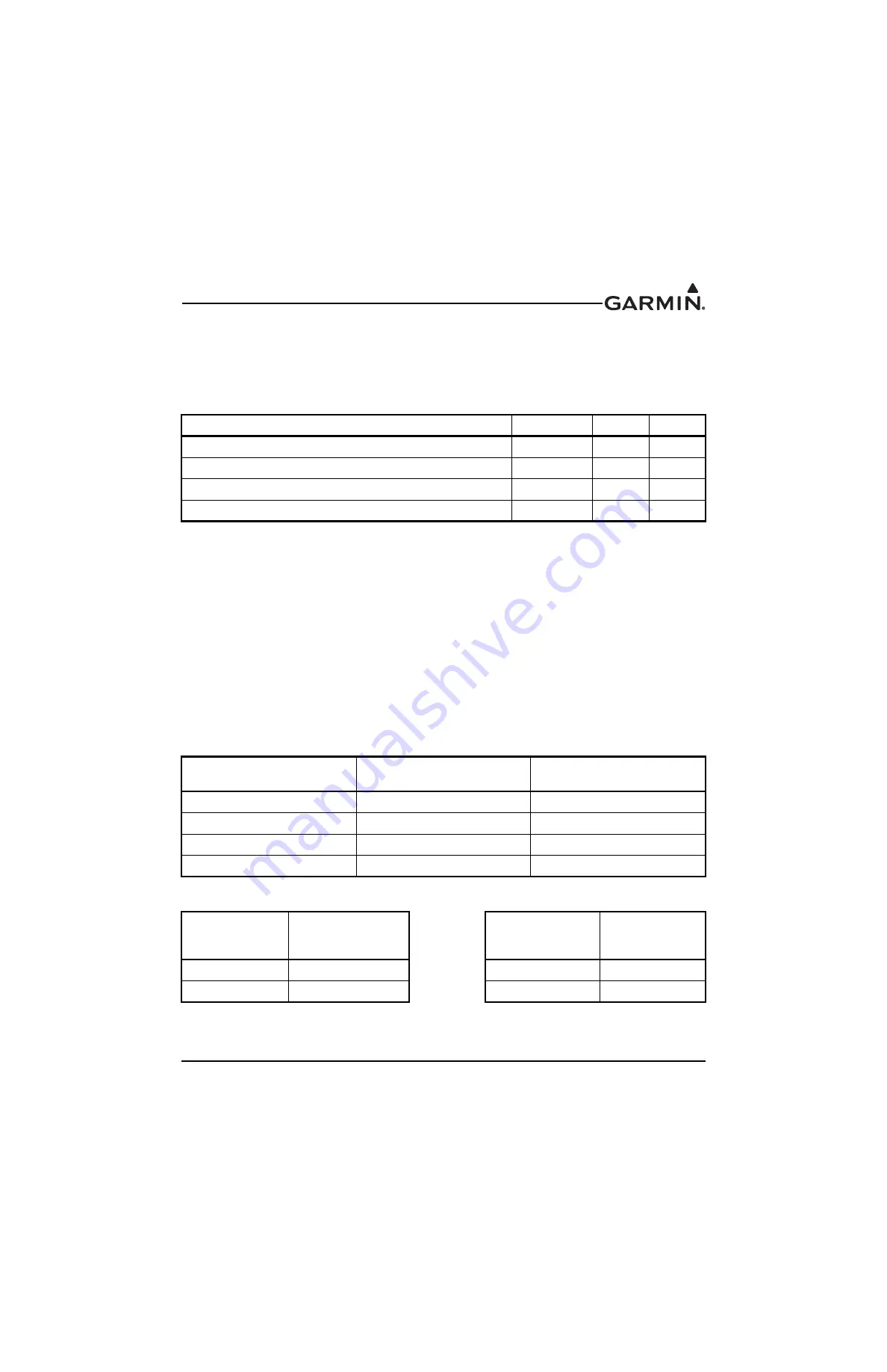
Configure the GDU 37X units per the following tables.
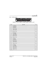
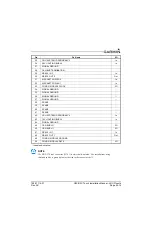
A GDU 37X can be manually placed in reversionary mode by wiring Pin 25 to a two pole switch that
toggles between open and ground. When the switch is open, the display will operate normally. When the
switch is grounded, the display changes to reversionary mode, showing the engine bar at the top of the
display and a split screen PFD and MFD below. Other displays in the system will not be affected by
manually placing a display into reversionary mode.
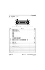
Do not connect a switch to ground for pins 9 or 10, doing so can cause communication errors.
Grounding pin 42 will place the GDU 37X in Demo mode, which is for in-store demonstration use only,
never ground pin 42 in an aircraft installation.
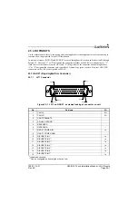
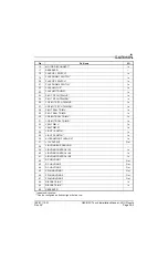
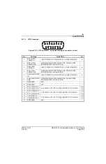
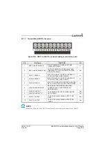
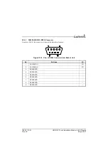
Pin Name
Connector
Pin
I/O
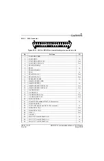
AIRCRAFT POWER 1
J3701
32
In
AIRCRAFT POWER 2
J3701
31
In
POWER GROUND
J3701
15
--
POWER GROUND
J3701
16
--
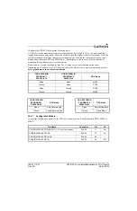
CDU SYSTEM ID
PROGRAM* 1, J3701 Pin 10
CDU SYSTEM ID
PROGRAM* 2, J3701 Pin 9
GDU Mode
Open
Open
MFD
Ground
Open
PFD1
Open
Ground
PFD2
Ground
Ground
Do Not Use
CDU SYSTEM ID
PROGRAM* 3
J3701 Pin 25
GDU Mode
CDU SYSTEM ID
PROGRAM* 4
J3701 Pin 42
GDU Mode
Open
Auto Reversionary
Open
Normal Operation
Ground
Forced Reversionary
Ground
Demo Mode

