background image

190-02692-00  Rev. A

Garmin G100 Pilot’s Guide for the Piper PA-32 Saratoga

75

FLIGHT INSTRUMENTS

SY

STEM

O

VER
VIEW

FLIGHT

INSTRUMENTS

EIS

AUDIO P

ANEL

& CNS

FLIGHT

MANA

GEMENT

HAZARD

AV

OID
ANCE

AFCS

ADDITIONAL

FEA
TURES

APPENDICES

INDEX

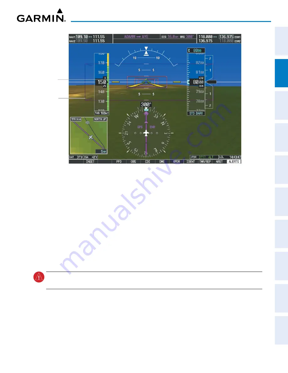
Flight Path 

Marker (FPM)

Figure 2-36  Flight Path Marker and Pathways

Pathway 

Box

ZERO PITCH LINE

The Zero Pitch Line is drawn completely across the display and represents the horizon when the terrain 

horizon is difficult to distinguish from other terrain being displayed.  It may not align with the terrain 
horizon, particularly when the terrain is mountainous or when the aircraft is flown at high altitudes.

HORIZON HEADING

The Horizon Heading is synchronized with the HSI and shows approximately 60 degrees of compass 

heading in 30 degree increments on the Zero Pitch Line.  Horizon Heading tick marks and digits appearing 
on the zero pitch line are not visible behind either the airspeed or altitude display.  Horizon Heading is used 
for general heading awareness, and is activated and deactivated by selecting the 

HRZN HDG

 Softkey.

TRAFFIC

 WARNING:


Intruder aircraft at or below 500 ft. AGL may not appear on the SVT display or may appear as a 

partial symbol.

Traffic symbols are displayed in their approximate locations as determined by the related traffic systems.  

Traffic symbols are displayed in three dimensions, appearing larger as they are getting closer, and smaller 
when they are further away.  Traffic within 250 feet laterally of the aircraft will not be displayed on the SVT 
display.  Traffic symbols and coloring are consistent with that used for traffic displayed in the Inset Map or 
MFD traffic page.  If the traffic altitude is unknown, the traffic will not be displayed on the SVT display.  For 
more details refer to the traffic system discussion in the Hazard Avoidance Section.

Summary of Contents for Cessna Caravan G1000

Page 1: ...iness Park Southampton Hampshire SO40 9LR U K Garmin Corporation No 68 Zhangshu 2nd Road Xizhi District New Taipei City Taiwan Contact Garmin Product Support or view warranty information at flygarmin...

Page 2: ......

Page 3: ...SYSTEM OVERVIEW FLIGHT INSTRUMENTS EIS AUDIO PANEL CNS FLIGHT MANAGEMENT HAZARD AVOIDANCE AFCS ADDITIONAL FEATURES APPENDICES INDEX...

Page 4: ......

Page 5: ...Garmin Skywatch and Stormscope are registered trademarks of L 3 Communications Ryan TCAD and Avidyne are registered trademarks of Avidyne Corporation CO Guardian is a trademark of CO Guardian Inc AC...

Page 6: ...anizations do not warrant or make any representations regarding its accuracy reliability or otherwise Licensee agrees not to sue AC U KWIK Organizations and to the maximum extent allowed by law to rel...

Page 7: ...the display WARNING Do not use data link weather information for maneuvering in near or around areas of hazardous weather Information contained within data link weather products may not accurately de...

Page 8: ...uvers to avoid terrain obstacles or traffic WARNING Do not use the Garmin SVT runway depiction as the sole means for determining the proximity of the aircraft to the runway or for maintaining the prop...

Page 9: ...ioning System and is solely responsible for its accuracy and maintenance The GPS system is subject to changes which could affect the accuracy and performance of all GPS equipment Portions of the syste...

Page 10: ...ment is required for compliance with established FAA regulatory guidance but does not constitute authorization to fly any and all terminal procedures that may be presented by the system It is the pilo...

Page 11: ...hin the Terrain database and the system s ability to process the data representing the affected areas NOTE The nose of the own ship symbol represents the location of the aircraft The center of any tra...

Page 12: ...Garmin G1000 Pilot s Guide for the Piper PA 32 Saratoga 190 02692 00 Rev A x WARNINGS CAUTIONS AND NOTES Blank Page...

Page 13: ...armin and or its third party providers You acknowledge that the Software is the property of Garmin and or its third party providers and is protected under the United States of America copyright laws a...

Page 14: ...Garmin G1000 Pilot s Guide for the Piper PA 32 Saratoga 190 02692 00 Rev A SOFTWARE LICENSE AGREEMENT xii Blank Page...

Page 15: ...Rev A Garmin G1000 Pilot s Guide for the Piper PA 32 Saratoga xiii REVISION INFORMATION Record of Revisions Part Number Revision Date Page Range Description 190 02692 00 A 2 21 20 All Initial Release...

Page 16: ...Garmin G1000 Pilot s Guide for the Piper PA 32 Saratoga 190 02692 00 Rev A xiv REVISION INFORMATION Blank Page...

Page 17: ...erting Functions 81 Marker Beacon Annunciations 81 Altitude Alerting 81 Low Altitude Annunciation 82 Minimum Altitude Alerting 82 2 5 Abnormal Operations 84 Abnormal GPS Conditions 84 Unusual Attitude...

Page 18: ...anning 249 Weight Caution And Warning Conditions 251 5 10 Trip PlanninG 252 Trip Planning 252 5 11 Abnormal Operation 256 Dead Reckoning 256 SECTION 6 HAZARD AVOIDANCE 6 1 SiriusXM Weather 260 Activat...

Page 19: ...6 Terminal Procedures Charts 397 Chart Options 401 Day Night View 401 8 4 SiriusXM Satellite Radio Entertainment 402 Activating SiriusXM Satellite Radio Services 402 Using SiriusXM Satellite Radio 403...

Page 20: ...Garmin G1000 Pilot s Guide for the Piper PA 32 Saratoga 190 02692 00 Rev A xviii TABLE OF CONTENTS Blank Page...

Page 21: ...to the pilot through large format displays The system consists of the following Line Replaceable Units LRUs GDU 1040 2 Primary Flight Display PFD and Multi Function Display MFD GTX 345R 1 Extended Squ...

Page 22: ...OAT probe This unit provides pressure altitude airspeed vertical speed and OAT information to the system and it communicates with both IAUs the PFD the MFD and the AHRS it also interfaces directly wit...

Page 23: ...2 GIA 63W Integrated Avionics Unit VHF COM GPS SBAS VOR LOC G S System Integration Micro processors GDU 1040 MFD Non Garmin Equipment GMA 1347 Audio Panel GDC 74A Air Data Computer GRS 77 Attitude He...

Page 24: ...Secure Digital SD cards and are located on the top right portion of the display bezels Each display bezel is equipped with two SD card slots SD cards are used for various databases system software up...

Page 25: ...ins to initialize and displays AHRS ALIGN Keep Wings Level The AHRS should display valid attitude and heading fields typically within the first minute of applying power The AHRS can align itself both...

Page 26: ...the Engine Indication System EIS see the EIS Section Both displays offer control for COM and NAV frequency selection Figure 1 5 Normal Operation REVERSIONARY DISPLAY OPERATION NOTE The system alerts t...

Page 27: ...and responsible LRUs For a detailed description of all annunciations and alerts refer to the Appendices Refer to the current version of the pertinent flight manual for additional information regarding...

Page 28: ...tem calibration incomplete or configuration module failure GPS information is either not present or is invalid for navigational use Note that ADAHRS AHRS utilizes GPS inputs during normal operation AD...

Page 29: ...south of Australia and New Zealand NOTE Aggressive maneuvering while AHRS is not operating normally may degrade AHRS accuracy In addition to using internal sensors the AHRS uses GPS information magne...

Page 30: ...values greater than approximately 200 knots is not guaranteed Under these rare conditions it is possible for in flight AHRS initialization to take an indefinite amount of time which would result in an...

Page 31: ...S2 for the 2 IAU may be viewed on the AUX GPS STATUS Page Viewing GPS receiver status information 1 Turn the large FMS Knob on the MFD to select the Auxiliary AUX Page Group see this section for infor...

Page 32: ...e is represented by an oval containing the Pseudorandom Noise PRN number i e satellite identification number Satellites whose signals are currently being used are represented by solid ovals SATELLITE...

Page 33: ...h Receiver Autonomous Integrity Monitoring RAIM is a GPS receiver function that performs a consistency check on all tracked satellites RAIM ensures the available satellite geometry allows the receiver...

Page 34: ...RAIM availability is computed one of the following is displayed COMPUTE RAIM RAIM has not been computed for the current waypoint time and date combination COMPUTING AVAILABILITY RAIM calculation in pr...

Page 35: ...AL STRENGTHS The AUX GPS STATUS Page can be helpful in troubleshooting weak or missing signal levels due to poor satellite coverage or installation problems As the GPS receiver locks onto satellites a...

Page 36: ...ID Knob Turn to control NAV audio volume shown in the NAV Frequency Box as a percentage Press to toggle Morse Code identifier audio on off 2 NAV Frequency Transfer Key Transfers the standby and activ...

Page 37: ...MENU Key Displays a context sensitive list of options for accessing additional features or making setting changes 14 PROC Key Gives access to IFR departure procedures DPs arrival procedures STARs and...

Page 38: ...level has a BACK Softkey which can be pressed to return to the previous level The ALERTS Softkey is visible at all softkey levels label changes if messages are issued Softkeys are listed in the follow...

Page 39: ...ging units to standard WIND Displays softkeys to select wind data parameters OPTN 1 Longitudinal and lateral components OPTN 2 Total direction and speed OPTN 3 Total direction with headwind and crossw...

Page 40: ...7 0 7 Use numbers to enter code IDENT Activates the Special Position Identification SPI pulse for 18 seconds identifying the transponder return on the ATC screen BKSP Removes numbers entered one at a...

Page 41: ...GATION MAP Page default MFD page softkeys are described here Level 1 Level 2 Description ENGINE Displays the DEC FUEL INC FUEL and RST FUEL softkeys available DEC FUEL Decreases gallons remaining by o...

Page 42: ...ICES INDEX Level 1 Level 2 Description DCLTR 3 Selects desired amount of map detail cycles through declutter levels DCLTR no declutter All map features visible DCLTR 1 Declutters land data DCLTR 2 Dec...

Page 43: ...there are no additional features or settings for the window or page selected Navigating a menu 1 Press the MENU Key to display the menu 2 Turn the FMS Knob to scroll through a list of available optio...

Page 44: ...e toward the letter Z followed by the digits zero through nine Turning the knob to the left scrolls through the characters in the opposite order 4 Turn the large FMS Knob to move the cursor to the nex...

Page 45: ...optional Terrain WPT Waypoint Airport Procedures Weather Information Pages Airport Information INFO 1 Softkey Airport Directory Information INFO 2 Softkey Departure Information DP Softkey Arrival Inf...

Page 46: ...ays the status of all system LRUs AUX SYSTEM SETUP PAGE The AUX SYSTEM SETUP Page allows management of the following system parameters Pilot Profile Status Time Format LOCAL or UTC Displayed Measureme...

Page 47: ...pilot profiles may be created selected renamed or deleted Figure 1 17 Pilot Profile Settings on AUX SYSTEM SETUP Page Creating a profile 1 Use the FMS Knob to select the AUX SYSTEM SETUP Page 2 Push t...

Page 48: ...Use the FMS Knob to select the AUX SYSTEM SETUP Page 2 Push the FMS Knob to activate the flashing cursor 3 Turn the large FMS Knob to highlight RENAME in the PILOT PROFILE Box 4 Press the ENT Key 5 In...

Page 49: ...ENT Key 5 If desired the profile name to be used after a profile has been imported can be changed by turning the FMS Knob to highlight the profile file name then use the FMS Knob to enter the new des...

Page 50: ...FMS Knobs then press the ENT Key with EXPORT highlighted 6 If the profile name to be exported is the same as an existing profile file name on the SD card the system displays an Overwrite existing fil...

Page 51: ...g the system time 1 Use the FMS Knob to select the AUX System Setup Page 2 Push the FMS Knob to activate the flashing cursor 3 Turn the large FMS Knob to highlight the TIME FORMAT Field 4 Turn the sma...

Page 52: ...e Map Ranges DIS GS TAS XTK Fields All Distances on MFD Altitude Buffer Distance System Setup Page Arrival Alert Trigger Distance System Setup Page All Speeds on MFD Airspeed Indicator True Airspeed P...

Page 53: ...ALERT Box 4 Turn the small FMS Knob to display and highlight the desired voice 5 Press the ENT Key GPS CDI The GPS CDI Box on the AUX SYSTEM SETUP Page allows the pilot to define the scale for the Cou...

Page 54: ...UP Page 2 Push the FMS Knob to activate the flashing cursor 3 Turn the large FMS Knob to highlight the CHANNEL SPACING Field in the COM CONFIG Box 4 Turn the small FMS Knob to select the desired spaci...

Page 55: ...list LRU INFO Box or AIRFRAME Box through which the FMS Knob can be used to scroll information Pressing the MFD1 DB Softkey label background changes to grey indicting the softkey is selected places t...

Page 56: ...er is counting up when reset the digits are zeroed Setting the generic timer PFD 1 Press the TMR REF Softkey 2 Turn the large FMS Knob to select the TIMER Field 00 00 00 3 Turn the small FMS Knob to e...

Page 57: ...or 3 Turn the small FMS Knob to select the timer counting direction UP DN and press the ENT Key 4 If a starting time is desired a Turn the large FMS Knob to highlight the 00 00 00 Field b Use the FMS...

Page 58: ...y the current time at the point of reset The format in which the time is displayed is controlled from the AUX SYSTEM SETUP Page Setting the departure timer starting criterion 1 Use the FMS Knob to sel...

Page 59: ...the ENT Key 9 For event based messages a Use the FMS Knob to enter the desired date DD MMM YY in the DATE Field and press the ENT Key b Press the ENT Key again or turn the large FMS Knob to move the...

Page 60: ...W FLIGHT INSTRUMENTS EIS AUDIO PANEL CNS FLIGHT MANAGEMENT HAZARD AVOIDANCE AFCS ADDITIONAL FEATURES APPENDICES INDEX TRIP STATISTICS Refer to the Flight Management Section of this manual for further...

Page 61: ...lighting 1 Press the PFD MENU Key to display the PFD SETUP MENU Window AUTO is now highlighted next to PFD DSPL 2 Turn the small FMS Knob to select MANUAL 3 Press the ENT Key 4 With the intensity valu...

Page 62: ...he Piper PA 32 Saratoga 190 02692 00 Rev A 42 SYSTEM OVERVIEW SYSTEM OVERVIEW FLIGHT INSTRUMENTS EIS AUDIO PANEL CNS FLIGHT MANAGEMENT HAZARD AVOIDANCE AFCS ADDITIONAL FEATURES APPENDICES INDEX Figure...

Page 63: ...pear on the PFD and are explained in other sections of this Pilot s Guide The following flight instruments and supplemental flight data are displayed on the PFD Airspeed Indicator showing Indicated Ai...

Page 64: ...ency Box 2 Airspeed Indicator 3 True Airspeed 4 Current Heading 5 Heading Bug 6 Horizontal Situation Indicator HSI 7 Outside Air Temperature OAT 8 Softkeys 9 System Time 10 Transponder Data Box 11 Tur...

Page 65: ...NAGEMENT HAZARD AVOIDANCE AFCS ADDITIONAL FEATURES APPENDICES INDEX Figure 2 2 Additional PFD Information 1 Selected Heading 2 Wind Data 3 Inset Map 4 Bearing Information Windows 5 Barometric Minimum...

Page 66: ...e Red Pointer at VNE Figure 2 3 Airspeed Indicator Color coded stripes appear on the Airspeed Indicator to show the operating ranges The low speed range stripe is red Normal operating range is green c...

Page 67: ...speed 4 Press the ENT Key or turn the large FMS Knob to highlight the ON OFF Field 5 Turn the small FMS Knob clockwise to ON or counterclockwise to OFF 6 To remove the window press the CLR Key or the...

Page 68: ...pitch marks and numeric labels are shown for every 10 up to 80 Minor pitch marks are shown for intervening five degree increments up to 25 below and 45 above the horizon line Between 20 below to 20 ab...

Page 69: ...is displayed above the Altimeter in the box indicated by a selection bug symbol A bug corresponding to this altitude is shown on the tape If the Selected Altitude exceeds the range shown on the tape...

Page 70: ...ing feet the system can show a metric overlay for the indicated and selected altitudes without changing the scale or display units of the Altimeter Displaying the metric altitude overlays 1 Press the...

Page 71: ...ey 3 Press the IN Softkey to display the barometric pressure setting in inches of mercury in Hg or press the HPA Softkey to display the barometric pressure setting in hectopascals hPa 4 Press the BACK...

Page 72: ...tor is only available when an SBAS signal such as WAAS EGNOS or MSAS is available The Vertical Deviation Indicator VDI is a magenta chevron to indicate the baro VNV vertical deviation when Vertical Na...

Page 73: ...tor Figure 2 10 Vertical Speed and Vertical Deviation Indications HORIZONTAL SITUATION INDICATOR HSI The Horizontal Situation Indicator HSI displays a rotating compass card in a heading up orientation...

Page 74: ...ss rose The Arc HSI contains a Course Pointer combined To From Indicator and a sliding deviation indicator and a deviation scale Upon station passage the To From Indicator flips and points to the tail...

Page 75: ...eturn the Course Pointer to the bearing of the active waypoint or navigation station Figure 2 13 Heading and Course Indications Magnetic Selected Heading Selected Course Current Heading Heading Bug Na...

Page 76: ...ponding to a predicted heading of 18 from the current heading At rates greater than four deg sec an arrowhead appears at the end of the magenta trend vector and the prediction is no longer valid Arrow...

Page 77: ...reat Circle Distance to Bearing Source When the NAV radio is tuned to an ILS frequency the bearing source and bearing pointer are removed from the HSI When NAV1 or NAV2 is the selected bearing source...

Page 78: ...uring a heading change of greater than 105 with respect to the course the CDI on the Arc HSI switches to the opposite side of the deviation scale and displays reverse sensing The Course Deviation Indi...

Page 79: ...cyan tuning box over the NAV2 standby frequency 3 Press the CDI Softkey a third time to return to GPS Selecting the CDI Softkey Cycles through Navigation Sources GPS Selected Figure 2 20 Selecting a N...

Page 80: ...F Glideslope Intercept Point GPS CDI SCALING When GPS is the selected navigation source the flight plan legs are sequenced automatically and annunciations appear on the HSI for the flight phase Flight...

Page 81: ...if 200 nm from nearest airport 0 3 nm Missed Approach 1 0 nm Approach 1 0 nm Terminal 1 0 nm Terminal 0 3 nm Departure CDI Full scale Deflection Refer to accompanying approach CDI scaling figures Onc...

Page 82: ...m During approach the CDI scale ramps down even further see following figures This transition normally occurs within 2 0 nm of the final approach fix FAF The CDI switches to approach scaling automatic...

Page 83: ...0 3 nm Flight phase annunciations are normally shown in magenta but when cautionary conditions exist the color changes to amber Table 2 1 Automatic GPS CDI Scaling OBS MODE NOTE VNV is inhibited whil...

Page 84: ...oftkey to select OBS Mode 2 Turn the CRS Knob to select the desired course to from the waypoint Push the CRS Knob to synchronize the Selected Course with the bearing to the next waypoint 3 Press the O...

Page 85: ...cations TEMPERATURE DISPLAYS The Outside Air Temperature OAT and deviation from International Standard Atmosphere ISA temperature are displayed in degrees Celsius C default or Fahrenheit F as selected...

Page 86: ...h headwind H or tailwind T and crosswind X components 4 To remove the window press the OFF Softkey 5 Press the BACK Softkey to return to the top level softkeys VERTICAL NAVIGATION VNV INDICATIONS When...

Page 87: ...ft 1 min before the next TOD due to flight plan change X X X VNV cancelled CNCL VNV Softkey pressed on MFD X X X Distance to active waypoint cannot be computed due to unsupported flight plan leg type...

Page 88: ...ning that the terrain elevation contours are stored in squares measuring nine arc seconds on each side is required for the operation of SVT Loss of any of the required data including temporary loss of...

Page 89: ...SVT feature softkeys The softkeys are labeled PATHWAY SYN TERR HRZN HDG and APTSIGNS The BACK Softkey returns to the previous level of softkeys Synthetic Terrain must be active before any other SVT f...

Page 90: ...N HDG Softkey The Horizon Heading display will cycle on or off with the HRZN HDG Softkey Activating and deactivating Airport Signs 1 Press the PFD Softkey 2 Press the SYN VIS Softkey 3 Press the SYN T...

Page 91: ...e color of the rectangular boxes may be magenta green or white depending on the route of flight and navigation source selected The active GPS or GPS overlay flight plan leg is represented by magenta b...

Page 92: ...raft at the altitude selected or programmed Descent and Approach Pathways are shown descending only for a programmed descent When the flight plan includes programmed descent segments Pathways are disp...

Page 93: ...Holding Point MAHP and are displayed as a level path at the published altitude for the MAHP or the Selected Altitude whichever is the highest If the initial missed approach leg is a Course to Altitud...

Page 94: ...he three dimensional terrain display The FPM is always available when the Synthetic Terrain feature is in operation The FPM represents the direction of the flight path as it relates to the terrain and...

Page 95: ...izon Heading tick marks and digits appearing on the zero pitch line are not visible behind either the airspeed or altitude display Horizon Heading is used for general heading awareness and is activate...

Page 96: ...ifier Between 8 nm and 15 nm RUNWAYS WARNING Do not use SVT runway depiction as the sole means for determining the proximity of the aircraft to the runway or for maintaining the proper approach path a...

Page 97: ...VT ALERTING Terrain alerting on the synthetic terrain display is triggered by Forward looking Terrain Avoidance FLTA alerts and corresponds to the red and yellow X symbols on the Inset Map and MFD map...

Page 98: ...two dimensional tower symbols found on the Inset Map and MFD maps and charts Obstacle symbols appear in the perspective view with relative height above terrain and distance from the aircraft Unlike t...

Page 99: ...tial Impact Point Obstacle Warning Obstacle Annunciation FIELD OF VIEW The PFD Field of View can be represented on the MAP NAVIGATION MAP Page Two dashed lines forming a V shape in front of the aircra...

Page 100: ...EW Option Field of View 3 Turn the FMS Knob to select Map in the GROUP Box and press the ENT Key 4 Turn the large FMS Knob to scroll through the Map Group fields to FIELD OF VIEW 5 Turn the small FMS...

Page 101: ...ALTITUDE ALERTING Altitude Alerting provides the pilot with a visual and aural alert when approaching the Selected Altitude Whenever the Selected Altitude is changed the Altitude Alerter is reset The...

Page 102: ...ure 2 45 Low Altitude on GPS SBAS Approach LOW ALT Annunciation MINIMUM ALTITUDE ALERTING For altitude awareness a minimum altitude can be set in the REFERENCES Window This can be based on barometric...

Page 103: ...d Setting the barometric minimum descent altitude and bug 1 Press the TMR REF Softkey 2 Turn the large FMS Knob to highlight the MINIMUMS Field 3 Turn the small FMS Knob to select the desired altitude...

Page 104: ...has been restored to within normal limits annunciation displayed for 5 seconds DR Upper right of aircraft symbol Dead Reckoning System is using projected position rather than GPS position to compute n...

Page 105: ...rack Available Heading and Track Unavailable SVT TROUBLESHOOTING SVT is intended to be used with traditional attitude heading obstacle terrain and traffic inputs SVT is disabled when valid attitude or...

Page 106: ...eriences unusual attitudes True Airspeed Ground Speed Traffic Annunciations Inset Map Outside Air Temperature OAT ISA Temperature Deviation Wind Data Selected Heading Display Selected Course Display T...

Page 107: ...32 Saratoga 87 FLIGHT INSTRUMENTS SYSTEM OVERVIEW FLIGHT INSTRUMENTS EIS AUDIO PANEL CNS FLIGHT MANAGEMENT HAZARD AVOIDANCE AFCS ADDITIONAL FEATURES APPENDICES INDEX Figure 2 51 Blue Sky Bar with Ful...

Page 108: ...Garmin G100 Pilot s Guide for the Piper PA 32 Saratoga 88 FLIGHT INSTRUMENTS SYSTEM OVERVIEW FLIGHT INSTRUMENTS EIS AUDIO PANEL CNS FLIGHT MANAGEMENT HAZARD AVOIDANCE AFCS ADDITIONAL FEATURES APPENDIC...

Page 109: ...system parameters and providing system alerts during all phases of flight The Engine Indication System EIS displays electrical fuel and engine information on the left side of the Multi Function Displa...

Page 110: ...v A 90 ENGINE INDICATION SYSTEM SYSTEM OVERVIEW FLIGHT INSTRUMENTS EIS AUDIO PANEL CNS FLIGHT MANAGEMENT HAZARD AVOIDANCE AFCS ADDITIONAL FEATURES APPENDICES INDEX 3 1 ENGINE DISPLAY Turbocharged Norm...

Page 111: ...gallons per hour GPH 5 Oil Temperature Displays oil temperature in degrees Fahrenheit F 6 Oil Pressure Displays oil pressure in pounds per square inch PSI 7 Exhaust Gas Temperature Displays Exhaust Ga...

Page 112: ...ng and indicates the hottest cylinder DEC FUEL Decreases the displayed fuel remaining GAL REM in 1 gal increments INC FUEL Increases the displayed fuel remaining GAL REM in 1 gal increments RST FUEL R...

Page 113: ...ained and displays the temperature deviation from peak D PEAK in degrees Fahrenheit beside the EGT display for the peaked cylinder When a cylinder peaks its number and display are indicated in cyan an...

Page 114: ...lly illustrates the aircraft s remaining range based heading groundspeed and wind direction and speed The Fuel Range Ring shifts position in relation to the aircraft according to the current calculate...

Page 115: ...n reversionary mode is identical to the normal EIS Display on the MFD The Lean Display presents temperature information and assistance for engine leaning The System Display shows the fuel calculations...

Page 116: ...GAL REM in 1 gal increments INC FUEL Increases the displayed fuel remaining GAL REM in 1 gal increments RST FUEL Resets displayed fuel remaining GAL REM to maximum fuel capacity Resets fuel used GAL...

Page 117: ...available after pressing the LEAN Softkey The CYL SLCT Softkey can be utilized to cycle through the cylinders and obtain information about a cylinder highlighted in cyan on the bar graph s For normall...

Page 118: ...190 02692 00 Rev A 98 ENGINE INDICATION SYSTEM SYSTEM OVERVIEW FLIGHT INSTRUMENTS EIS AUDIO PANEL CNS FLIGHT MANAGEMENT HAZARD AVOIDANCE AFCS ADDITIONAL FEATURES APPENDICES INDEX Turbocharged Normall...

Page 119: ...d Aircraft Maximum manifold pressure range displayed in red 2 Tachometer Displays engine tachometer in revolutions per minute RPM 3 Fuel Quantity Displays left L and right R FUEL QTY fuel quantity in...

Page 120: ...using the following softkeys DEC FUEL Decreases totalizer based fuel remaining in one gallon increments INC FUEL Increases totalizer based fuel remaining in one gallon increments RST FUEL Resets total...

Page 121: ...a 101 ENGINE INDICATION SYSTEM SYSTEM OVERVIEW FLIGHT INSTRUMENTS EIS AUDIO PANEL CNS FLIGHT MANAGEMENT HAZARD AVOIDANCE AFCS ADDITIONAL FEATURES APPENDICES INDEX Turbocharged Normally aspirated Figur...

Page 122: ...Displays the calculated amount of fuel used based on the totalizer fuel flow 6 Calculated Fuel Remaining Displays the amount of fuel remaining set by the pilot and adjusted for fuel burn 7 Oil Pressu...

Page 123: ...lay MFD Integrated Avionics Unit 2 Audio Panel Mode S Transponder The MFD PFD controls are used to tune the communication transceivers and navigation radios The audio panel provides the traditional au...

Page 124: ...L AND CNS SYSTEM OVERVIEW FLIGHT INSTRUMENTS EIS AUDIO PANEL CNS FLIGHT MANAGEMENT HAZARD AVOIDANCE AFCS ADDITIONAL FEATURES APPENDICES INDEX MFD PFD CONTROLS AND FREQUENCY DISPLAY Figure 4 1 PFD Cont...

Page 125: ...ncies for the COM transceiver large knob for MHz small knob for kHz Push to move the tuning box cyan box and Frequency Transfer Arrow between COM1 and COM2 7 COM Frequency Transfer Key Transfers the s...

Page 126: ...cts the 1 transmitter for transmitting COM1 receive is simultaneously selected when this key is pressed allowing received audio from the 1 COM receiver to be heard COM2 receive can be added by pressin...

Page 127: ...14 NAV1 When selected audio from the 1 NAV receiver can be heard 15 ADF Turns optional ADF receiver audio on or off 16 NAV2 When selected audio from the 2 NAV receiver can be heard 17 AUX Not used in...

Page 128: ...COM1 MIC or COM2 MIC Key Both active COM frequencies appearing in white indicates that no COM radio is selected for transmitting PA Key is selected on the audio panel Frequencies in the standby field...

Page 129: ...uency Transfer Key to transfer the frequency to the active field 3 Adjust the volume level with the COM VOL SQ Knob 4 Push the COM VOL SQ Knob to turn automatic squelch on and off Turn the VOL SQ Knob...

Page 130: ...d from the following NEAREST AIRPORTS Window PFD WPT AIRPORT INFORMATION Page NRST NEAREST AIRPORTS Page NRST NEAREST FREQUENCIES Page NRST NEAREST AIRSPACES Page AUTO TUNING FROM THE PFD COM frequenc...

Page 131: ...matically loaded into the COM Frequency Box from pages in the NRST or WPT page group by highlighting the frequency and pressing the ENT Key Auto tuning a COM frequency from the WPT and NRST Pages 1 Fr...

Page 132: ...FMS Knob to scroll through the menu options 3 Press the ENT Key to place the cursor on the desired selection 4 Scroll through the frequency selections with the FMS Knob or the ENT Key 5 Press the ENT...

Page 133: ...e Press ENT Key to load frequency into COM Standby Field Press INFO 1 Softkey for WPT AIRPORT DIRECTORY Page Selected airport identifier and information Runway information Press Frequency Transfer Key...

Page 134: ...FREQUENCY SPACING The G1000 COM radios can tune either 25 kHz spacing 118 000 to 136 975 MHz or 8 33 kHz spacing 118 000 to 136 990 MHz for 760 channel or 3040 channel configuration When 8 33 kHz chan...

Page 135: ...omplete the channel spacing selection While the COM CONFIG Window is selected the softkeys are blank Figure 4 14 AUX SYSTEM SETUP Page Select 8 33 kHz or 25 0 kHz COM Frequency Channel Spacing AUTOMAT...

Page 136: ...RES APPENDICES INDEX VOLUME COM radio volume level can be adjusted from 0 to 100 using the VOL SQ Knob Turning the knob clockwise increases volume turning the knob counterclockwise decreases volume Wh...

Page 137: ...or LOC2 If NAV2 is selected a green double line arrow labeled either VOR2 or LOC2 is displayed on the HSI and the active NAV2 frequency is displayed in green GPS If GPS Mode is selected a magenta sing...

Page 138: ...sh the small NAV Knob to transfer the frequency tuning box and Frequency Transfer Arrow between the upper and lower radio frequency fields Figure 4 19 Switching NAV Tuning Boxes Push the NAV Knob to s...

Page 139: ...enroute navigation the NAV frequency is entered automatically into the NAV standby frequency field During approach activation the NAV frequency is entered automatically into the NAV active frequency f...

Page 140: ...through the frequency selections with the FMS Knob or the ENT Key 5 Press the ENT Key to load the NAV frequency into the standby field of the selected NAV radio 6 Press the Frequency Transfer Key to t...

Page 141: ...n the VOR frequency Figure 4 24 Loading the NAV Frequency from the NRST NEAREST VOR Page Press the ENT Key to load the frequency into the NAV Standby Field Press the VOR Softkey to Place the Cursor on...

Page 142: ...00 Pilot s Guide for the Piper PA 32 Saratoga 122 AUDIO PANEL AND CNS SYSTEM OVERVIEW FLIGHT INSTRUMENTS EIS AUDIO PANEL CNS FLIGHT MANAGEMENT HAZARD AVOIDANCE AFCS ADDITIONAL FEATURES APPENDICES INDE...

Page 143: ...standby frequency fields the approach frequency is transferred or loaded into both active frequency fields If the current CDI navigation source is NAV1 the approach frequency is transferred to the NA...

Page 144: ...ource for the bearing pointer The G1000 system tunes the ADF receiver optional and DME transceiver optional The ADF is tuned by entering the frequency in the ADF standby frequency field of the ADF DME...

Page 145: ...the next digit position 5 Press the ENT Key to complete data entry for the standby frequency Figure 4 28 Entering ADF Standby Frequencies Press the ENT Key to complete ADF frequency entry Turn the sm...

Page 146: ...e interrupted carrier beacon stations used in various parts of the world ANT BFO Antenna Beat Frequency Oscillator The ADF bearing pointer parks on the HSI at 90 degrees while an audible tone is provi...

Page 147: ...ME Modes The following DME transceiver pairing can be selected NAV1 Pairs the DME frequency from the selected NAV1 frequency NAV2 Pairs the DME frequency from the selected NAV2 frequency HOLD When in...

Page 148: ...itter the extended squitter is transmitted periodically and contains information such as altitude barometric and GPS GPS position and aircraft identification The purpose of extended squitter is to pro...

Page 149: ...de Mode or manual Standby ON and Altitude Modes The Standby On and ALT softkeys can be accessed by selecting the XPDR Softkey Selecting a transponder mode 1 Select the XPDR Softkey to display the Tran...

Page 150: ...her aircraft Figure 4 34 ON Mode Airborne ON Mode No altitude reporting On Ground ON Mode No altitude reporting ALTITUDE MODE ALT Mode can be selected at any time by pressing the ALT Softkey When ALT...

Page 151: ...y to display the Transponder Code Selection Softkeys for digit entry 3 Press the digit softkeys to enter the code in the code field When entering the code the next softkey in sequence must be pressed...

Page 152: ...Air Traffic Control ATC The indication distinguishes the identing transponder from all the others on the air traffic controller s screen The IDENT Softkey appears on all levels of transponder softkeys...

Page 153: ...io panel a person listening on a monaural headset hears only the left channel in both ears If a monaural headset is used at one of the passenger positions any other passenger using a stereo headset he...

Page 154: ...radios aural alerts and warnings and everyone else The pilot and passengers can hear the selected radios and communicate with each other When both the PILOT and COPLT Annunciations are illuminated the...

Page 155: ...out once per second while the PTT is depressed Figure 4 43 PA Key Selected for Cabin Announcements PA Key is selected on the audio panel CLEARANCE RECORDER AND PLAYER The audio panel contains a digita...

Page 156: ...th the pilot and the copilot can transmit simultaneously over separate radios The pilot can still monitor NAV1 NAV2 ADF DME and MKR Audio as selected but the copilot is only able to monitor COM2 Press...

Page 157: ...the copilot when the PILOT Key Annunciation is illuminated MUSIC 1 Muting MUSIC 1 muting occurs when aircraft radio or marker beacon activity is heard MUSIC 1 is always soft muted when an interruption...

Page 158: ...lication the following steps aid in maximizing the use of the audio panel as well as preventing pilot and copilot induced issues These preflight procedures should be performed each time a pilot boards...

Page 159: ...C or COM2 MIC Key Annunciation on the audio panel flashes as long as the PTT Key remains stuck Figure 4 47 Stuck Microphone Alert COM TUNING FAILURE In case of a COM system tuning failure the emergenc...

Page 160: ...rmin G1000 Pilot s Guide for the Piper PA 32 Saratoga 140 AUDIO PANEL AND CNS SYSTEM OVERVIEW FLIGHT INSTRUMENTS EIS AUDIO PANEL CNS FLIGHT MANAGEMENT HAZARD AVOIDANCE AFCS ADDITIONAL FEATURES APPENDI...

Page 161: ...INSET Softkey Pressing the INSET Softkey again then pressing the OFF Softkey removes the Inset Map The Navigation Map displays aviation data e g airports VORs airways airspaces geographic data e g ci...

Page 162: ...formation on the Navigation Map Active Flight Plan Leg Navigation Map Aviation Data Geographic Data Topographic Data Hazard Data Navigation Data Bar Aircraft Icon at Present Position Navigation Page T...

Page 163: ...inimum Safe Altitude ENR ETE to Final Destination TAS True Air Speed ESA Enroute Safe Altitude TKE Track Angle Error ETA Estimated Time of Arrival TRK Track ETE Estimated Time Enroute VSR Vertical Spe...

Page 164: ...s to the following maps unless otherwise noted All Map Group Pages MAP All Flight Plan Group Pages FPL All Waypoint Group Pages WPT DIRECT TO Window AUX TRIP PLANNING Page PFD Inset Map All Nearest Gr...

Page 165: ...re 5 7 MAP SETUP Window Map Group Orientation Field Map Group Auto North Up Field Changing the Navigation Map orientation 1 With the MAP NAVIGATION MAP Page displayed press the MENU Key The cursor fla...

Page 166: ...range is indicated in the lower right corner of the map and represents the top to bottom distance covered by the map When the map range is decreased to a point that exceeds the capability of the syst...

Page 167: ...ease to a point where situational awareness may not be what is desired Increase the minimum look ahead time to a value that limits the auto zoom to a minimum range that provides acceptable situational...

Page 168: ...n to any location on the navigation map or between any two points on the navigation map View obstacle airspace and airway information When the panning function is selected by pushing the Joystick the...

Page 169: ...p Pointer is placed on an object the name of the object is highlighted even if the name was not originally displayed on the map When any map feature or object is selected on the map display pertinent...

Page 170: ...name and class of airspace the ceiling in feet above Mean Sea Level MSL and the floor in feet MSL Figure 5 11 Navigation Map Map Pointer on Airspace Map Pointer on Airspace Information about Airspace...

Page 171: ...for the Measure Pointer is provided in a window at the top of the navigation map Measuring bearing and distance between any two points 1 Press the MENU Key with the MAP NAVIGATION MAP Page displayed...

Page 172: ...isable Profile View Or 1 Press the MENU Key 2 Select Show Profile View or Hide Profile View and press the ENT Key Navigation Map Black Background TOPO Off Figure 5 13 Navigation Map Topographic Data T...

Page 173: ...Selecting a topographical data range TOPO DATA 1 Press the MENU Key with the MAP NAVIGATION MAP Page displayed The cursor flashes on the Map Setup option 2 Press the ENT Key The MAP SETUP Window is d...

Page 174: ...nob to return to the MAP NAVIGATION MAP Page MAP SYMBOLS This section discusses the types of land and aviation symbols that can be displayed Each listed type of symbol can be turned on or off and the...

Page 175: ...and Symbol Information AVIATION SYMBOLS The following items are configured on the aviation menu Aviation Symbols Text label size can be None Small Medium Med or Large Lrg Symbol Default Range nm Maxim...

Page 176: ...ge nm CL C CTA see below Class C Airspace CL C 200 500 Control Area CTA CL A D see below Terminal Radar Service Area TRSA Controlled Traffic Region CTR and Class A CL A 150 300 Class D Restricted Area...

Page 177: ...oads High Altitude Airways are drawn in green When both types of airways are displayed High Altitude Airways are drawn on top of Low Altitude Airways When airways are selected for display on the map t...

Page 178: ...rway Range Airway Display Selection Off All LO Only HI Only The airway range is the maximum map range on which airways are displayed Selecting an airway range LOW ALT AIRWAY or HI ALT AIRWAY 1 Press t...

Page 179: ...menu is displayed and the cursor flashes on the Map Setup option 2 Press the ENT Key The MAP SETUP Window is displayed 3 Highlight the LAND DATA Field 4 Select On or Off 5 Push the FMS Knob to return...

Page 180: ...u Option Figure 5 17 Navigation Map Declutter Level Indications Declutter Level Navigation Map Page Menu DCLTR Softkey Decluttering the map Press the DCLTR Softkey with the Navigation Map Page display...

Page 181: ...tter 2 Declutter 3 Data Link Radar Precipitation X Data Link Lightning X Graphical METARs X Airports X Safe Taxi X Runway Labels X TFRs X Restricted X MOA Military X User Waypoints X X Latitude Longit...

Page 182: ...CNS Section Map Pointer Displayed when panning see Using Map Displays in Flight Management Measuring Pointer Displayed when measuring bearing and distance see Using Map Displays in Flight Management...

Page 183: ...ND VECTOR The map displays a wind vector arrow in the upper right hand portion of the display Wind vector information is displayed as a white arrow pointing in the direction in which the wind is movin...

Page 184: ...vigation Map Nav Range Ring Nav Range Ring Range radius NOTE The Nav Range Ring is not displayed on theWaypoint Information pages Nearest pages or Direct to Window map Displaying removing the Nav Rang...

Page 185: ...Map Fuel Range Ring Range to Reserve Fuel Time to Reserve Fuel Total Endurance Range Displaying removing the fuel range ring and selecting a fuel range time 1 Press the MENU Key with the MAP NAVIGATI...

Page 186: ...as two dashed lines forming a V shape in front of the aircraft symbol on the map This is only available if SVT is installed on the aircraft Figure 5 22 Navigation Map Field of View Lateral Field of V...

Page 187: ...ltitude The location will be shown as a cyan arc when the aircraft is actually climbing or descending Figure 5 23 Navigation Map Selected Altitude Intercept Arc Selected Altitude Intercept Arc Display...

Page 188: ...me of the facility or by entering the city name See the System Overview Section for detailed instructions on entering data in the system As a waypoint identifier facility name or location is entered t...

Page 189: ...requencies COM NAV and lighting review runways and review instrument procedures that may be involved in the flight plan See the Audio Panel and CNS Section for more information on loading frequencies...

Page 190: ...t Information ID Facility City Usage Type Region Lat Long Elev Fuel Available Time Zone UTC Offset COM NAV Freq Info Identification Frequency Availability Additional Information Softkeys The following...

Page 191: ...titudes TPA Aircraft Class Altitude Runway Headings Length Width Obstructions Surface Phones Phone Fax Numbers Weather Service Type Frequency Phone Number Obstructions General Airport Obstructions Hou...

Page 192: ...The Destination Airport is displayed The Airport Frequencies Box uses the descriptions and abbreviations listed in the following table Communication Frequencies Navigation Frequencies Approach Arrival...

Page 193: ...AIRPORT INFORMATION Window on PFD Airport Information Usage Time Elev Region Airport Information Lat Long Airport Information ID Type City Facility The NRST NEAREST AIRPORTS Page on the MFD is first i...

Page 194: ...return to the NEAREST AIRPORTS Window press the ENT Key with the cursor on BACK or press the CLR Key The cursor is now on the next airport in the nearest airports list Repeatedly pressing the ENT Key...

Page 195: ...with small runways or runways that are not appropriately surfaced from being displayed Default settings are 0 feet or meters for runway length and HARD SOFT for runway surface type Selecting nearest...

Page 196: ...dial to VOR Distance to VOR Intersection Info Region Lat Long Selecting an intersection 1 With the WPT INTERSECTION INFORMATION Page displayed enter an identifier in the INTERSECTION Box 2 Press the E...

Page 197: ...aircraft position Reference VOR Info Identifier Type symbol VOR Frequency Bearing Distance to VOR Intersection Lat Long NDBS The WPT NDB INFORMATION Page is used to view information about NDBs In add...

Page 198: ...cursor The NRST NEAREST NDB Page can be used to quickly find a NDB close to the flight path In addition to displaying a map of the surrounding area the page displays information for up to 25 nearest N...

Page 199: ...includes only DME it is displayed as VOR DME In addition to displaying a map of the currently selected VOR and surrounding area the WPT VOR INFORMATION Page displays VOR information in four boxes lab...

Page 200: ...can be used to quickly find a VOR station close to the aircraft Also a NAV frequency from a selected VOR station can be loaded from the NRST NEAREST VOR Page In addition to displaying a map of the su...

Page 201: ...tion Country Bearing Distance to VRP from aircraft position Lat Long Selecting a VRP 1 With the WPT VRP INFORMATION Page displayed enter the identifier or the name of the VRP in the VRP Box 2 Press th...

Page 202: ...list the information is dashed Figure 5 39 NRST NEAREST VRP Page Nearest VRP VRP Information VRP Name Country Lat Long VRP Identifier Symbol Bearing Distance to VRP from aircraft position USER WAYPOIN...

Page 203: ...nt User Waypoint Info Identifier Temporary Normal Waypoint Type Reference Wpt Info Identifier Rad Dist or Identifiers Radials or Region Lat Long Selecting a User Waypoint 1 With theWPT USERWPT INFORMA...

Page 204: ...cters 3 Press the ENT Key The current aircraft position is the default location of the new waypoint 4 If desired define the type and location of the waypoint in one of the following ways Select RAD RA...

Page 205: ...NTS window using the FMS Knobs Or Select LAT LON using the small FMS Knob press the ENT Key and enter the latitude and longitude into the INFORMATION window using the FMS Knobs 6 Press the ENT Key to...

Page 206: ...RMATION window using the FMS Knobs 6 Press the ENT Key to accept the new waypoint 7 If desired change the storage method of the waypoint to temporary by moving the cursor to the TEMPORARY Field and pr...

Page 207: ...ed comment is based on the reference point used to define the waypoint The default type of user waypoint normal or temporary can be changed using the user waypoint information page menu Temporary user...

Page 208: ...DANCE AFCS ADDITIONAL FEATURES APPENDICES INDEX NOTE The option to Delete All User Waypoints is not available while the aircraft is in flight Deleting all user waypoints 1 Highlight a User Waypoint in...

Page 209: ...ng TMA Class C CTA Class A Class D Restricted Prohibited MOA Military and other airspace provided by the navigation database Some examples of typical airspaces are depicted below See the Map Symbols p...

Page 210: ...Message Comments INSIDE ARSPC Inside airspace The aircraft is inside the airspace ARSPC AHEAD Airspace ahead less than 10 minutes Special use airspace is ahead of aircraft The aircraft penetrates the...

Page 211: ...fo Name Proximity Ahead Inside Ahead 2nm Within 2nm Time till Intercept only if Ahead or Ahead 2nm Airspace Vertical Limits Ceiling Floor Airspace Agency Info Airspace Type Controlling Agency Softkeys...

Page 212: ...airspace the airspace boundary is shown normally If the current aircraft altitude is not within 1100 feet of the vertical boundaries of the airspace the airspace boundary is shown subdued Figure 5 45...

Page 213: ...vertical navigation VNV direct to creates a descent path and provides guidance to stay on the path from the current altitude to a selected altitude at the direct to waypoint Vertical navigation is ba...

Page 214: ...process 3 Press the ENT Key The ACTIVATE Field is highlighted 4 Press the ENT Key to activate the direct to Any waypoint contained in the active flight plan can be selected as a direct to waypoint fro...

Page 215: ...int is the active flight plan waypoint if a flight plan is active or a blank waypoint field Direct to requests on any WPT page defaults to the displayed waypoint Selecting any waypoint as a direct to...

Page 216: ...ayed on ACTIVATE 5 Press the ENT Key again to activate the direct to Reselecting the direct course from the current position 1 Press the Key The DIRECT TO Window is displayed with the destination fiel...

Page 217: ...APPENDICES INDEX 6 Press the ENT Key The cursor is now flashing in the VNV offset distance field 7 Enter the desired along track distance before the waypoint 8 Press the ENT Key The ACTIVATE Field is...

Page 218: ...eading leg Roll Steering Path Turning path currently flown Turning path for the next flight plan leg Turning path beyond the next flight plan leg Turn Anticipation Arc Displayed when sequencing to the...

Page 219: ...ted the airways need to be reloaded also Each airway segment is reloaded from the database given the entry waypoint the airway identifier and the exit waypoint This reloads the sequence of waypoints b...

Page 220: ...ntifier Airway Identifier Desired Track to Waypoint Distance to Waypoint Waypoint Altitude Constraint Vertical Navigation Profile Active Vertical WPT Alt ID Vertical Speed Target Flight Path Angle Ver...

Page 221: ...n can be configured to show cumulative distance over the length of the flight plan or the distance for each leg of the flight plan and the active flight plan can be viewed in a narrow or wide view In...

Page 222: ...n Cumulative Distance LEG LEG Softkey CUM Softkey Switching between wide and narrow view 1 Press the FPL Key on the MFD to display the FPL ACTIVE FLIGHT PLAN Page 2 Press the VIEW Softkey to display t...

Page 223: ...rning it clockwise displays a blank Waypoint Information Window turning it counter clockwise displays the WAYPOINT INFORMATION Window with a waypoint selection submenu allowing selection of active fli...

Page 224: ...waypoints within airways and procedures If the number of waypoints in the flight plan exceeds 100 the message Flight plan is full Remove unnecessary waypoints appears and the new waypoint s are not a...

Page 225: ...the flight plan to add the new waypoint The new waypoint is placed directly in front of the highlighted waypoint 5 Turn the small FMS Knob to display the WAYPOINT INFORMATION Window Turning it clockw...

Page 226: ...he ENT Key The user waypoint is created with a name of USRxxx using the next available in sequence and is added to the end of the active flight plan Removing Waypoints Individual waypoints and airways...

Page 227: ...Over Waypoint Fly Over Waypoint Active Leg to PNH Geometry cannot support fly by to the following leg PNH to ILOZA Roll Steering to next leg Roll Steering until path aligns with course leg PNH to ILOZ...

Page 228: ...Push the FMS Knob to activate the cursor not required on the PFD 3 Turn the large FMS Knob to highlight the waypoint after the desired airway entry point If this waypoint is not a valid airway entry...

Page 229: ...AVOIDANCE AFCS ADDITIONAL FEATURES APPENDICES INDEX Figure 5 59 Selecting Airway Exit Point Airway Entry Waypoint Selected Airway Airway Exit Points Available Selected Exit Point Selected Airway Exit...

Page 230: ...With OK highlighted press the ENT Key To cancel the request press the CLR Key or highlight CANCEL and press the ENT Key 5 Push the FMS Knob to remove the flashing cursor Collapsing Airways The system...

Page 231: ...s leg sequencing will be suspended Activating a flight plan leg 1 Press the FPL Key 2 Push the FMS Knob to activate the cursor not required on the PFD and turn the large FMS Knob to highlight the dest...

Page 232: ...5 62 Along Track Offset Along Track Offset Waypoint and Distance Along Track Offset Waypoint and Distance from Flight Plan Waypoint Entering an along track offset distance 1 Press the FPL Key 2 Push t...

Page 233: ...than 120 or the parallel tracks overlap as a result of the course change NOTE Vertical navigation is unavailable while the Parallel Track feature is active Activating parallel track 1 Press the FPL K...

Page 234: ...k between two fixes TF or a course to a fix DF leg the status indicates the system is unable to activate the parallel track because parallel track is not available for the active leg type Cancelling p...

Page 235: ...at any active flight plan waypoint at the aircraft present position or at a direct to waypoint Waypoint Selected Hold At Waypoint Menu Selection Figure 5 64 Creating a User Defined Holding Pattern at...

Page 236: ...to select RIGHT or LEFT turn direction and press the ENT Key 9 Use the FMS Knobs to edit the EXPECT FURTHER CLEARANCE Time EFC TIME and press the ENT Key 10 Press the ENT Key while LOAD is highlighted...

Page 237: ...S ADDITIONAL FEATURES APPENDICES INDEX Hold At Present Position Menu Selection Figure 5 65 Creating a User Defined Holding Pattern at the Aircraft Present Position Location of Hold Expect Further Clea...

Page 238: ...ed at the direct to waypoint If the direct to waypoint is part of the active flight plan the HOLD is inserted into the active flight plan If the direct to waypoint is not part of the active flight pla...

Page 239: ...TURES APPENDICES INDEX Waypoint Selected Hold At Direct To Waypoint Selection Figure 5 66 Creating a User Defined Holding Pattern at a Direct To Waypoint Location of Hold Expect Further Clearance Time...

Page 240: ...conds Figure 5 67 Arrival Alert Settings Enabling disabling the Arrival Alert 1 Use the FMS Knob to select the AUX SYSTEM SETUP Page 2 Push the FMS Knob momentarily to activate the flashing cursor 3 T...

Page 241: ...ngtheFMSKnob pressthe ENT Key select another flight plan slot and press the IMPORT Softkey again 7 Turn the small FMS Knob to highlight the desired flight plan for importing 8 Press the ENT Key to ini...

Page 242: ...e EXPORT Softkey or press the MENU Key select Export Flight Plan 7 If desired change the name for the exported file by turning the large FMS Knob to the left to highlight the name then use the small a...

Page 243: ...he SD card contains more waypoints than the system can support The flight plan was imported with as many waypoints as possible Some waypoints not loaded Waypoints locked The flight plan on the SD card...

Page 244: ...the system is turned off overwritten when another flight plan is activated Additionally the system allows the pilot to delete the active flight plan Deleting the active flight plan suspends navigation...

Page 245: ...MS Knob clockwise one click to display the FPL FLIGHT PLAN CATALOG Page 3 Push the FMS Knob to activate the cursor and turn the FMS Knob to highlight the desired flight plan 4 Information is displayed...

Page 246: ...and activate stored flight plan window is displayed 4 With OK highlighted press the ENT Key To cancel the request press the CLR Key or highlight CANCEL and press the ENT Key Copying a stored flight pl...

Page 247: ...Changing the active flight plan comment 1 Press the FPL Key on the MFD to display the FPL ACTIVE FLIGHT PLAN Page 2 Push the FMS Knob to activate the cursor and turn the large FMS Knob to highlight th...

Page 248: ...ath is defined by a line joining two waypoints with specified altitudes or as a vertical angle from a specified waypoint altitude The vertical waypoints are integrated into the active flight plan Figu...

Page 249: ...plan from current position to the vertical direct to waypoint not just along the leg for the direct to waypoint A direct to with altitude constraint activated by pressing the Key also provides vertica...

Page 250: ...instance manually entered or retrieved from the published altitudes in the navigation database The navigation database only contains altitudes for procedures that call for Cross at altitudes If the p...

Page 251: ...above mean sea level MSL or height above ground level AGL AGL format is only available for airport waypoints An altitude constraint is invalid if Meeting the constraint requires the aircraft to climb...

Page 252: ...FMS Knob to choose MSL or AGL and press the ENT Key to accept the altitude 5 Press the ENT Key to accept the altitude constraint Removing undesignating an altitude constraint 1 Press the FPL Key for t...

Page 253: ...ilable on the Active Flight Plan Page for quick activation when needed Activating also adds the procedure to the end of the flight plan but immediately begins to provide guidance to the first waypoint...

Page 254: ...Repeat Step 5 until desired information has been viewed for the chosen procedure 7 Press the INFO 1 or INFO 2 Softkey to return to the WPT AIRPORT INFORMATION PAGE DEPARTURES A Departure Procedure DP...

Page 255: ...ANCE AFCS ADDITIONAL FEATURES APPENDICES INDEX Figure 5 75 Departure Selection Departure Airport Departure Preview Available Procedure Actions Departure Choices Loaded Procedures Procedure Loading Pag...

Page 256: ...layed listing the departure procedure 4 With OK highlighted press the ENT Key To cancel the removal request highlight CANCEL and press the ENT Key 5 Push the FMS Knob to remove the flashing cursor ARR...

Page 257: ...TRUMENTS EIS AUDIO PANEL CNS FLIGHT MANAGEMENT HAZARD AVOIDANCE AFCS ADDITIONAL FEATURES APPENDICES INDEX Figure 5 77 Arrival Selection Destination Airport Arrival Preview Available Procedure Options...

Page 258: ...and for information on the display of vertical guidance on the PFD see the Flight Instruments Section See the Audio Panel CNS Section for information on selecting and tuning a NAV receiver INSTRUMENT...

Page 259: ...published DA LPV Table 5 10 Approach Service Levels The system GPS receivers will use Satellite Based Augmentation SBAS when available Some approaches require the use of SBAS for lateral and or vertic...

Page 260: ...V More than 1 min prior to the FAF HSI displays amber LP V VDI displays NO GP None N A Within 1 min prior to the FAF HSI displays magenta LNAV CDI is removed VDI displays NO GP Acknowledge message to...

Page 261: ...the approach In many cases it may be easiest to load the full approach while still some distance away enroute to the destination airport Later if vectored to final use the steps below to select Activa...

Page 262: ...CHANNEL Field b Use the FMS Knob to enter the approach channel number and press the ENT Key to accept the approach channel number The airport and approach are selected 4 Select a transition if requir...

Page 263: ...to select the temperature and press the ENT Key Or To skip setting minimums press the ENT Key The LOAD Field is highlighted 8 Press the ENT Key with LOAD highlighted to load the approach procedure or...

Page 264: ...he Missed Approach Point MAP waypoint sequencing will continue along the approach to the missed approach If the missed approach is not activated prior to the MAP the system will enter SUSP Mode once t...

Page 265: ...ch Hold Point MAHP In this case the altitude would be appear in the list of waypoints as 5500 Again if the aircraft altitude is lower than the prescribed altitude after crossing the MAP a direct to is...

Page 266: ...Knob to change the TEMP AT airport Field The compensated altitude is computed as the temperature is selected 5 Press the ENT Key ACTIVATE COMPENSATION is highlighted 6 Press the ENT Key The compensat...

Page 267: ...EIS AUDIO PANEL CNS FLIGHT MANAGEMENT HAZARD AVOIDANCE AFCS ADDITIONAL FEATURES APPENDICES INDEX Temperature Compensation Selected Figure 5 82 Temperature Compensation Selected Temperature FAF Altitud...

Page 268: ...ELECT APPROACH Press the ENT Key 3 If necessary use the FMS Knob and the ENT Key to select the desired airport approach and transition 4 Use the FMS Knob to place the flashing cursor in the MINIMUMS B...

Page 269: ...lculated by the system and dashes for those fields are displayed Figure 5 85 WEIGHT AND FUEL PLANNING Page Payload Calculator Basic EmptyWeight Entry Pilot StoresWeight Entry Basic OperatingWeight Cal...

Page 270: ...3 Press the ENT Key to confirm the entry 4 Push the FMS Knob to remove the flashing cursor if desired Entering the average passenger weight 1 To activate the cursor push the FMS Knob Highlight the AT...

Page 271: ...uel reserves amount 3 Press the ENT Key to confirm the entry 4 Push the FMS Knob to remove the flashing cursor if desired Synchronizing the fuel on board with the actual measured fuel on board Select...

Page 272: ...atedAirspeed IndicatedAltitude Barometric Pressure TotalAirTemperature Softkeys Automatic Manual Page Mode Flight Plan Waypoint Mode Preview of Selected Flight Plan Flight Plan Leg Trip Planning Page...

Page 273: ...the endpoints of the active leg Some of the calculated trip statistics are dashed when the selected leg of the active flight plan has already been flown Desired Track Desired Track is shown degrees an...

Page 274: ...ted by taking the time of fuel endurance and subtracting the estimated time enroute to the end of the selected leg Fuel required for trip FUEL REQ This value is calculated by multiplying the time to g...

Page 275: ...ys the selected data Selecting waypoints for waypoint mode 1 From the AUX TRIP PLANNING Page press the WPTS Softkey or press the MENU Key highlight Waypoints Mode and press the ENT Key The cursor is p...

Page 276: ...through DR while there is no heading and or airspeed data available should not be used for navigation DRModeisinherentlylessaccuratethanthestandardGPS SBASModeduetothelackofsatellitemeasurements neede...

Page 277: ...TS EIS AUDIO PANEL CNS FLIGHT MANAGEMENT HAZARD AVOIDANCE AFCS ADDITIONAL FEATURES APPENDICES INDEX Distance Bearing GPS Navigation Lost Message Dead Reckoning Annunciation Figure 5 89 Dead Reckoning...

Page 278: ...Guide for the Piper PA 32 Saratoga 190 02692 00 Rev A 258 FLIGHT MANAGEMENT SYSTEM OVERVIEW FLIGHT INSTRUMENTS EIS AUDIO PANEL CNS FLIGHT MANAGEMENT HAZARD AVOIDANCE AFCS ADDITIONAL FEATURES APPENDIC...

Page 279: ...with regard to potential hazards to flight safety associated with weather terrain and air traffic Weather GDL 69 69A SXM SiriusXM Weather Subscription Optional Garmin GTX 345R Flight Information Serv...

Page 280: ...provide continuous reception capabilities at any altitude throughout North America Services from SiriusXM are subscription based For more information on specific service packages visit www siriusxm co...

Page 281: ...ducts offered in the chosen SiriusXM Weather product subscription package press the LOCK Softkey 5 Turn the large FMS Knob to highlight YES 6 To complete activation press the ENT Key Figure 6 1 AUX XM...

Page 282: ...displays a weather product icon and product age The product age is the elapsed time in minutes since the weather data provider compiled the weather product The product age display does not indicate t...

Page 283: ...iriusXM Lightning XM LTNG 30 Cell Movement CELL MOV 30 SIGMETs AIRMETs SIG AIR 60 Meteorological Aerodrome Report METARs 90 City Forecast CITY 90 Surface Analysis SFC 60 Freezing Levels FRZ LVL 120 Wi...

Page 284: ...MAP Page MAP WEATHER DATA LINK XM Page WPT WEATHER INFORMATION Page AUX TRIP PLANNING Page Nearest Page Group Flight Plan Pages NEXRAD No Radar Coverage Cloud Top CLD TOP Echo Top ECHO TOP SiriusXM L...

Page 285: ...from the display If a map range larger than the weather product map range setting is selected the weather product data is removed from the map The menus also provide the ability to enable disable the...

Page 286: ...A LINK XM Page and on most MFD pages displaying a navigation map Viewing legends for displayed weather products on the MAP WEATHER DATA LINK XM Page 1 Select the MAP WEATHER DATA LINK XM Page 2 Press...

Page 287: ...site is 250 nm Individual NEXRAD sites supply the network with radar images and the images from each radar site may arrive at the network at different rates and times Periodically the weather data pr...

Page 288: ...s radar returns from the lowest antenna tilt angle known as base reflectivity The display of the information is color coded to indicate the intensity of the echoes and the type or precipitation if kno...

Page 289: ...ong radar reflection while dry hail does not Both wet and dry hail can be extremely hazardous The different NEXRAD echo intensities are measured in decibels dB relative to reflectivity Z NEXRAD measur...

Page 290: ...adar images Ground clutter Strobes and spurious radar data Sun strobes when the radar antenna points directly at the sun Interference from buildings or mountains which may cause shadows Metallic dust...

Page 291: ...nada No Coverage Above 55 N ECHO TOPS NOTE Echo Tops cannot be displayed at the same time as Cloud Tops or NEXRAD data on the MAP WEATHER DATA LINK XM Page The Echo Tops weather product shows the loca...

Page 292: ...y of these weather products is mutually exclusive When Echo Tops is enabled on the MAP WEATHER DATA LINK XM Page the system disables the NEXRAD and Cloud Tops weather products Figure 6 9 Echo Tops Leg...

Page 293: ...caling to represent altitude display of these weather products is mutually exclusive When Cloud Tops is activated on the MAP WEATHER DATA LINK XM Page the system disables the Echo Tops weather product...

Page 294: ...P WEATHER DATA LINK XM Page select the LEGEND Softkey when SiriusXM Lightning is selected for display Figure 6 13 Lightning Legend CELL MOVEMENT The Cell Movement weather product shows the location an...

Page 295: ...DATA LINK XM Page For Cell Movement to be displayed on maps other than the MAP WEATHER DATA LINK XM Page Cell Movement must be enabled in the Navigation Map Setup Menu see the procedure Setting up an...

Page 296: ...ress the LEGEND Softkey when SIGMETs and AIRMETs are selected for display Figure 6 18 SIGMET AIRMET Legend Figure 6 17 Sample SIGMET Text METARS AND TAFS NOTE Atmospheric pressure as reported for META...

Page 297: ...sion The system displays TAF information only in its original form when a TAF is available Displaying METAR and TAF text 1 On the MAP WEATHER DATA LINK XM Page press the METAR Softkey 2 Push the Joyst...

Page 298: ...FD METAR flags appears next to waypoints in the flight plan with an associated METAR Displaying original METAR text on the FPL ACTIVE FLIGHT PLAN Page 1 Select the FPL ACTIVE FLIGHT PLAN Page on the M...

Page 299: ...orecast weather conditions Forecasts are available for intervals of 12 24 36 and 48 hours Figure 6 22 Current Surface Analysis and City Forecast Weather Products Displaying Surface Analysis and City F...

Page 300: ...on at which the first isotherm is found When no data is displayed for a given altitude the data for that altitude has not been received or is out of date and has been removed from the display New data...

Page 301: ...Press the MORE WX Softkey 3 Press the WIND Softkey changes based on selected altitude Softkey 4 Select the desired altitude level SFC surface up to 42 000 feet Press the NEXT or PREV Softkey to cycle...

Page 302: ...ing table Headwind Symbol Tailwind Symbol Headwind Tailwind Component None None Less than 5 knots 5 knots 10 knots 50 knots Table 6 3 Profile View Headwind Tailwind Component Symbols Showing Hiding Pr...

Page 303: ...to select the Profile Group and press the ENT Key 5 Turn the large FMS Knob to select Profile Winds 6 Turn the small FMS Knob to select On or Off 7 Push the FMS Knob or CLR Key to return to the MAP N...

Page 304: ...ATHER DATA LINK XM Page 2 Press the MORE WX Softkey 3 Press the COUNTY Softkey To display the County Warnings legend press the LEGEND Softkey when County Warnings are selected to be displayed Figure 6...

Page 305: ...e same time as NEXRAD data is selected for display Current Icing Product CIP data shows a graphical view of the icing environment Icing severity is displayed in four categories light moderate severe a...

Page 306: ...he NEXRAD weather product is selected for display The Turbulence weather product identifies the potential for erratic movement of high altitude air mass associated winds Turbulence is classified as li...

Page 307: ...when Turbulence is selected for display Figure 6 36 Turbulence Legend PIREPS AND AIREPS Pilot Weather Reports PIREPs describe in flight weather conditions encountered by pilots When significant weath...

Page 308: ...THER DATA LINK XM Page 2 Press the MORE WX Softkey 3 Press the AIREPS or PIREPS Softkey 4 Push the Joystick and pan to the desired weather report A gray circle appears around the weather report when i...

Page 309: ...CE AFCS ADDITIONAL FEATURES APPENDICES INDEX Figure 6 38 PIREP Text on the MAP WEATHER DATA LINK XM Page Decoded PIREP Text Original PIREP Text Selected PIREP Age of report in HH MM To display the PIR...

Page 310: ...ts TFRs may be issued at any time and TFR data displayed is only intended to supplement official TFR information obtained from Flight Service Stations FSS and air traffic control The age of TFR data i...

Page 311: ...om the map Maps other than the MAP NAVIGATION MAP Page use settings based on those selected for the MAP NAVIGATION MAP Page Setting up and customizing TFR data for maps on which TFR data can be displa...

Page 312: ...eception may be affected by factors including altitude and terrain Reception of FIS B weather data occurs automatically without any pilot action FIS B broadcasts provide weather data in a repeating cy...

Page 313: ...eather product is not refreshed within the Expiration Time intervals the data is considered expired and is removed from the display This ensures the displayed data is consistent with FIS B broadcast d...

Page 314: ...the MENU Key 3 With Map Setup highlighted press the ENT Key 4 Turn the small FMS Knob to select the Weather Group and press the ENT Key 5 Turn the large FMS Knob or press the ENT Key to scroll throug...

Page 315: ...s default value turn the large FMS Knob to highlight the desired field to restore 6 Press the MENU Key 7 Turn the large FMS Knob if needed to highlight Restore Selection Default to restore only the hi...

Page 316: ...Viewing legends for displayed weather products on the MAP WEATHER DATA LINK FIS B Page 1 Select the MAP WEATHER DATA LINK FIS B Page 2 Press the LEGEND Softkey to display the legends for the displayed...

Page 317: ...the images from each radar site may arrive at the network at different rates and times Periodically the weather data provider to FIS B compiles the available individual site images from the network t...

Page 318: ...nk FIS B Page 2 Press the NEXRAD Softkey This softkey becomes the US Softkey A mosaic of NEXRAD data for the continental United States CONUS is displayed 3 To display the regional version of the NEXRA...

Page 319: ...NEXRAD legend press the LEGEND Softkey when the NEXRAD weather product is enabled No Radar Coverage Inside Coverage Boundary Boundary of Regional Radar Coverage Area Figure 6 46 NEXRAD Weather Produc...

Page 320: ...asured in decibels dB relative to reflectivity Z NEXRAD measures the radar reflectivity ratio or the energy reflected back to the radar receiver designated by the letter Z The value of Z increases as...

Page 321: ...Report or SPECI includes the code SPECI in the report and may be issued if critical information has changed after the issuance of a METAR The system displays colored flags at airports with report s av...

Page 322: ...X Softkey to select the WPT WEATHER INFORMATION Page 2 Push the FMS Knob to display the cursor 3 Use the FMS Knob to enter the desired airport and press the ENT Key 4 Use the FMS Knob or the ENT Key t...

Page 323: ...LEGEND Softkey when METARs are selected for display The METAR flag color is determined by the information in the METAR text The system displays a gray METAR flag when the METAR text does not contain e...

Page 324: ...age AUX ADS B STATUS Page Item Status Message Description FIS B Weather Status FIS B Processing ENABLED The FIS B weather feature is enabled to process and display FIS B weather products DISABLED The...

Page 325: ...SiriusXM or Garmin Connext Weather NOTE When using Stormscope there are several atmospheric phenomena in addition to nearby thunderstorms that can cause isolated discharge points in the strike displa...

Page 326: ...ormscope data on or off STRMSCP MODE Selects the CELL or STRIKE mode of lightning activity Cell mode identifies clusters or cells of electrical activity Strike mode indicates the approximate location...

Page 327: ...NDEX Figure 6 51 MAP NAVIGATION MAP Page with Stormscope Lightning Data If heading input is lost strikes and or cells must be cleared manually after the execution of each turn This is to ensure the st...

Page 328: ...total 200 nm in front and 200 nm behind the 500 nm range in North Up orientation shows all the data At a map range of less than 25 nm Stormscope lightning data is not displayed but can still be prese...

Page 329: ...6 52 MAP STORMSCOPE Page Changing between cell and strike mode 1 Select the MAP STORMSCOPE Page 2 Press the MODE Softkey The CELL and STRIKE softkeys are displayed 3 Press the CELL Softkey to display...

Page 330: ...NT Key Or 1 Select the MAP STORMSCOPE Page 2 Press the CLEAR Softkey Changing the viewing mode between 360 and 120 1 Select the MAP STORMSCOPE Page 2 Press the VIEW Softkey The 360 and ARC softkeys ar...

Page 331: ...e database Terrain Proximity displays altitudes of terrain and obstructions relative to the aircraft position and altitude with reference to a database that may contain inaccuracies Terrain and obstru...

Page 332: ...tude Red terrain is above or within 100 ft below the aircraft altitude Yellow terrain is between 100 ft and 1000 ft below the aircraft altitude Black terrain is more than 1000 ft below the aircraft al...

Page 333: ...within the setting limit Maps besides the MAP TERRAIN PROXIMITY Page use settings based on those selected for the MAP NAVIGATION MAP Page The maximum display ranges for obstacles on each map are depen...

Page 334: ...out clutter from the basemap Aviation data airports VORs and other NAVAIDs can be displayed for reference Aircraft orientation on this map is always heading up unless there is no valid heading Two vie...

Page 335: ...errain Legend Map Range Rings Map Orientation Current Aircraft GPS derived GSL Altitude Red Terrain Above or Within 100 Below the Aircraft Altitude Black Terrain More than 1000 Below the Aircraft Alti...

Page 336: ...n reducing controlled flight into terrain CFIT Do not confuse Terrain SVS with TAWS B TAWS B is more sophisticated and robust and it is TSO C151b certified Although the terrain and obstacle color map...

Page 337: ...onditions DISPLAYING TERRAIN SVS DATA Terrain SVS uses yellow caution and red warning to depict terrain and obstacles with heights greater than 200 feet above ground level AGL Alerts are given relativ...

Page 338: ...the data is removed from the map For terrain data the enable disable function applies only to the MFD while the range setting also affects the PFD Inset Map Terrain data can be selected for display i...

Page 339: ...are available relative to the position of the aircraft the 360 default display and the radar like ARC 120 display Map range is adjustable with the Joystick from 1 to 200 nm as indicated by the map ran...

Page 340: ...d 1000 Below the Aircraft Altitude Red Terrain Above or Within 100 Below the Aircraft Altitude Black Terrain Terrain More than 1000 Below the Aircraft Altitude Map Range Arc Terrain Legend Map Orienta...

Page 341: ...ANCE AFCS ADDITIONAL FEATURES APPENDICES INDEX Press the CLR Key returns to the currently viewed page or Press the ENT Key accesses the MAP TERRAIN SVS Page PFD Alert Annunciation Figure 6 60 Terrain...

Page 342: ...on may appear on the PFD next to the altimeter if the current aircraft altitude is at least 164 feet below the prescribed altitude at the Final Approach Fix See the Flight Instruments Section for deta...

Page 343: ...ated when the projected vertical flight path is calculated to come within minimum clearance altitudes in the following figure Required Terrain Clearance 0 100 200 300 400 500 600 700 800 0 5 10 15 20...

Page 344: ...d When the GPS signal is re established and the aircraft is within the database coverage area the voice alert Terrain System Available is generated Alert Cause PFD MFD Alert Annunciation MAP TERRAIN S...

Page 345: ...S B uses information provided from the GPS receiver to provide a horizontal position and altitude GPS altitude is derived from satellite measurements GPS altitude is then converted to the height above...

Page 346: ...ls in the following figure and tables are used to represent terrain obstacles and potential impact points Figure 6 64 Terrain Altitude Color Correlation for TAWS Unlighted Obstacle Lighted Obstacle Ob...

Page 347: ...AWS B icon with the terrain legend when terrain and obstacles are enabled on MFD maps The legend appears without the terrain icon on the dedicated MAP TAWS B Page Figure 6 65 TAWS B Icon and Legend Th...

Page 348: ...Key 4 Turn the small FMS Knob to select the Map Group and press the ENT Key 5 Turn the large FMS Knob or press the ENT Key to scroll through product selections TERRAIN DATA Enables disables display of...

Page 349: ...no valid heading Two views are available relative to the position of the aircraft the 360 default display and the radar like ARC 120 display Map range is adjustable with the Joystick from one to 200 n...

Page 350: ...es Between 100 and 1000 Below Aircraft Altitude TAWS B ALERTS Alerts are issued when flight conditions meet parameters that are set within TAWS B software algorithms TAWS B alerts typically employ a C...

Page 351: ...PANEL CNS FLIGHT MANAGEMENT HAZARD AVOIDANCE AFCS ADDITIONAL FEATURES APPENDICES INDEX Alert Annunciation Figure 6 67 TAWS B PFD Alert Annunciation Figure 6 69 MAP NAVIGATION MAP Page After TAWS B Po...

Page 352: ...bstacle Clearance Warning ROC PULL UP OBSTACLE PULL UP or OBSTACLE AHEAD PULL UP Obstacle Obstacle Pull Up Pull Up or Obstacle Ahead Pull Up Obstacle Ahead Pull Up Imminent Obstacle Impact Warning IOI...

Page 353: ...shown on TAWS B Page and the MAP NAVIGATION MAP Page when Terrain is enabled Alerts with multiple messages are configurable at installation and are installation dependent Alerts for the default config...

Page 354: ...sued when the aircraft is below the elevation of a terrain or obstacle cell in the aircraft s projected path ITI and IOI alerts are accompanied by a potential impact point displayed on the TAWS B Page...

Page 355: ...opriate When PDA and FLTA alerts are inhibited the alert annunciation TAWS INH is shown on the PFD and MFD Figure 6 73 TAWS Alerting Disabled TAWS B Inhibited Annunciation Inhibiting enabling TAWS B P...

Page 356: ...ndred voice alert NEGATIVE CLIMB RATE AFTER TAKEOFF ALERT The Negative Climb Rate NCR After Takeoff alert also referred to as Altitude Loss After Takeoff provides alerts when the system determines the...

Page 357: ...cts a self test of its visual annunciations and voice alerts The system test can also be manually initiated The system issues a voice alert when the test has concluded TAWS B System Testing is disable...

Page 358: ...rated in the annunciation window and on the MAP TAWS B Page The voice alert TAWS Not Available is generated When sufficient GPS signal is received and the aircraft is within the terrain database cover...

Page 359: ...and press the ENT Key Enabling Disabling Profile View Terrain on the Navigation Map when Profile View is enabled 1 Select the MAP NAVIGATION MAP Page 2 Press the MAP Softkey 3 Press the TERRAIN Softk...

Page 360: ...Enabled Altitude Scale Distance Scale Profile Path Range Markers Navigation Map Range Obstacles with heights greater than 200 feet AGL appear relative to aircraft altitude along the altitude scale The...

Page 361: ...able when Profile View is enabled White range markers both edges of the Profile Path match the range markers along the distance scale inside the Profile View Window The Profile View distance must be a...

Page 362: ...Systems TCAS and toTIS Aircraft without altitude reporting capability are shown without altitude separation data or climb descent indication NOTE TIS is disabled if another traffic system is installe...

Page 363: ...capability appear without altitude separation or climb descent information DISPLAYING TRAFFIC DATA Traffic information can be displayed on the following maps when TIS is operating PFD Inset Map MAP NA...

Page 364: ...NT Key to scroll through product selections TRAFFIC Turns the display of traffic data on or off TRAFFIC MODE Selects the traffic mode for display select from All Traffic Displays all traffic TA ONLY D...

Page 365: ...ce Alert Status Select to Mute TIS Not Available Voice Alert Figure 6 81 MAP TRAFFIC MAP Page Traffic Advisory 500 Below Climbing Non Threat Traffic 2500 Above Descending Range Marking Rings TIS ALERT...

Page 366: ...c or requesting aircraft is above the radar site in the cone of silence and out of range of an adjacent site Traffic or requesting aircraft is below radar coverage In flat terrain the coverage extends...

Page 367: ...eing received from the transponder but a failure is detected in the data stream FAILED The transponder has failed UNAVAILABLE TIS is unavailable or out of range Contact a service center or Garmin deal...

Page 368: ...tandby STANDBY also shown in white in center of page TIS Failed FAIL Table 6 22 TIS Modes Switching between TIS modes 1 Select the MAP TRAFFIC MAP Page 2 Press the STANDBY or OPERATE Softkey select a...

Page 369: ...rs if traffic data is not refreshed within 6 seconds If after another 6 seconds data is not received traffic is removed from the display The quality of displayed traffic information is reduced as the...

Page 370: ...s relieve the pilot s responsibility to see and avoid other aircraft NOTE Pilots should be aware of on board traffic system limitations These systems require transponders of other aircraft to respond...

Page 371: ...otentially hazardous intruding aircraft if the closing rate distance and vertical separation meet TA criteria A Traffic Advisory that is beyond the selected display range off scale is indicated by a h...

Page 372: ...e seconds and remains displayed until no TAs are detected in the area The PFD Inset Map is automatically displayed with TA traffic If the bearing of TA traffic cannot be determined a yellow text banne...

Page 373: ...n seconds to complete When the system test is initiated a test pattern of traffic symbols is displayed on the MAP TRAFFIC MAP Page The traffic system issues a voice alert when the test is completed If...

Page 374: ...TANDBY Softkey forces the unit into Standby Mode Switching from Operating Mode to Standby Mode On the MAP TRAFFIC MAP Page press the STANDBY Softkey Or 1 Press the MENU Key and turn the small FMS knob...

Page 375: ...y Off Scale 400 Below Level Traffic Display Range Rings Non Threat Traffic Altitude Not Reported Non Threat Traffic 2500 Above Descending Operating Mode Displaying traffic on the MAP TRAFFIC MAP Page...

Page 376: ...to 2700 feet below the aircraft Typically used during enroute phase of flight BELOW Displays non threat and proximity traffic from 2700 feet above the aircraft to 9000 feet below the aircraft Typicall...

Page 377: ...T HAZARD AVOIDANCE AFCS ADDITIONAL FEATURES APPENDICES INDEX Figure 6 86 MAP TRAFFIC MAP Page with Flight IDs Enabled Flight ID Enabling Disabling Flight ID Display On the MAP TRAFFIC MAP Page press t...

Page 378: ...ollowing maps on the MFD when the unit is operating MAP NAVIGATION MAP Page MAP TRAFFIC MAP Page AUX TRIP PLANNING Page Nearest Pages FPL ACTIVE FLIGHT PLAN Page System Pages Traffic information can a...

Page 379: ...press the ENT Key 4 Turn the small FMS Knob to select the Traffic Group and press the ENT Key 5 Turn the large FMS Knob or press the ENT Key to scroll through the selections TRAFFIC Turns the display...

Page 380: ...ing the INSET Softkey A traffic map will appear in heading up orientation Traffic information can also be overlaid with navigation topographic and optional data link weather information Displaying tra...

Page 381: ...fic unit Table 6 28 Traffic Failure Annunciations The annunciations to indicate the status of traffic information appear in a banner at the lower left corner of maps on which traffic can be displayed...

Page 382: ...ety and efficiency ADS B relies on the automatic broadcast of position reports by aircraft surface vehicles and transmitters on fixed objects These broadcasts contain information such as GPS position...

Page 383: ...aracteristics of the ground station providing the TIS B service ADS B WITH TAS When an optional Skywatch SKY497 Traffic Advisory System TAS is also installed and operating with the optional ADS B Traf...

Page 384: ...y Any Any 25 850 0 20 5 Unavailable 1000 2350 Any Any 25 850 0 20 5 Unavailable Unavailable Terminal Any 25 850 0 20 6 Unavailable or 2350 Unavailable or 2350 Not approach and not Terminal including u...

Page 385: ...til no TAs are detected in the area The PFD Inset Map is automatically displayed with TA traffic If the bearing of TA traffic cannot be determined an amber text banner will be displayed in the center...

Page 386: ...hen the SURF applications is on the system displays airborne and on the ground traffic At a MAP TRAFFIC MAP Page range of two nm or less the airport environment including taxiways and runways appears...

Page 387: ...thout directional information Non threat traffic with directional information Points in the direction of the intruder aircraft track Non threat traffic without directional information Traffic located...

Page 388: ...Above Descending Non Threat Traffic Altitude Not Reported Proximity Advisory with Directional Information 500 Above Level Enabling disabling the display of ADS B traffic 1 Select the MAP TRAFFIC MAP P...

Page 389: ...affic is displayed TA s occurring outside of these limits will always be shown Changing the altitude range 1 On the MAP TRAFFIC MAP Page select the ALT MODE Softkey 2 Press one of the following Softke...

Page 390: ...ted the vectors extending from the traffic symbols depict the traffic s reported track and speed over the ground When Relative Motion Vectors are selected the vectors extending from the traffic symbol...

Page 391: ...s the motion vector relative to own aircraft OFF Disables the display of the motion vector Or a Select the MAP TRAFFIC MAP Page b Press the MENU Key c Turn the small FMS Knob to highlight Relative Mot...

Page 392: ...bove or below the corresponding traffic symbol on the MAP TRAFFIC MAP Page when this option is enabled Figure 6 95 MAP TRAFFIC MAP Page with Flight IDs Enabled Flight ID Enabling Disabling Flight ID D...

Page 393: ...the Joystick clockwise to increase the range of the traffic map or counter clockwise to decrease the range ADDITIONAL TRAFFIC DISPLAYS The MAP TRAFFIC MAP Page is the principal map page for viewing tr...

Page 394: ...N MAP Page 2 Press the MENU Key 3 With Map Setup highlighted press the ENT Key 4 Turn the small FMS Knob to select the Traffic Group and press the ENT Key 5 Turn the large FMS Knob or press the ENT Ke...

Page 395: ...g is selected the data is removed from the map Maps besides the Traffic Map Page use settings based on those selected for the MAP NAVIGATION MAP Page The PFD can display traffic on either the inset na...

Page 396: ...f ADS B OFF ADS B TRFC OFF ADS B Traffic Not Available ADS B N A NO TRK HDG ADS B Failed ADS B FAIL FAILED See Table 6 44 for additional failure annunciations Table 6 33 Traffic Modes If the traffic u...

Page 397: ...tes distance in nm altitude separation in hundreds of feet and altitude trend arrow climbing descending TRFC FAIL Traffic unit has failed unit is self reporting a failure or sending incorrectly format...

Page 398: ...application is not available Required input data is not available or the application has failed NOT CONFIGURED Traffic application is not available because it has not been configured If this annuncia...

Page 399: ...e S TEC Fifty Five X Refer to the approved S TEC Fifty Five X Pilot s Pertinent Flight Manual for a comprehensive list of annunciations and operating instructions In addition to the redundant status m...

Page 400: ...for the Piper PA 32 Saratoga 190 02692 00 Rev A 380 AUTOMATIC FLIGHT CONTROL SYSTEM SYSTEM OVERVIEW FLIGHT INSTRUMENTS EIS AUDIO PANEL CNS FLIGHT MANAGEMENT HAZARD AVOIDANCE AFCS ADDITIONAL FEATURES A...

Page 401: ...p view of the airport layout can be seen The FliteCharts and optional ChartView provide on board electronic terminal procedures charts Electronic charts offer the convenience of rapid access to essent...

Page 402: ...lex ramp areas Airport Hot Spots are outlined to caution pilots of areas on an airport surface where positional awareness confusion or runway incursions happen most often Hot Spots are defined with a...

Page 403: ...lected for easy recognition of decluttering level Pressing the DCLTR Softkey removes the taxiway markings and airport feature labels Pressing the DCLTR 1 Softkey removes VOR station ID the VOR symbol...

Page 404: ...S Knob to select the Aviation Group and press the ENT Key 4 Turn the large FMS Knob to scroll through the Aviation Group options to SAFETAXI 5 Turn the small FMS Knob to display the range of distances...

Page 405: ...ies Therefore when the aircraft symbol reaches a chart boundary line or inset box the aircraft symbol is removed from the display Note the grey shading is for illustrative purposes only and will not a...

Page 406: ...ing the CHRT OPT Softkey advances to the next level of softkeys ALL HEADER PLAN PROFILE MINIMUMS FIT WDTH FULL SCN and BACK While viewing the CHRT OPT Softkeys after 45 seconds of softkey inactivity t...

Page 407: ...individual chart the banner UNABLE TO DISPLAY CHART is then displayed Figure 8 8 Unable To Display Chart Banner When a chart is not available by pressing the SHW CHRT Softkey or selecting a Page Menu...

Page 408: ...ion 6 Turn the large FMS Knob to select the Approach Box 7 Turn the small FMS Knob to show the approach chart selection choices 8 Turn either FMS Knob to scroll through the available charts 9 Press th...

Page 409: ...d chart is the airport diagram the INFO Softkey has no effect The aircraft position is shown in magenta on the ChartView diagrams when the location of the aircraft is within the chart boundaries The D...

Page 410: ...from the SiriusXM Data Link Receiver when available Weather information is available only when a SiriusXM Data Link Receiver is installed and the SiriusXM Weather subscription is current Recent NOTAMS...

Page 411: ...ftkey changes the chart size to fit the available screen width Pressing the FULL SCN Softkey alternates between removing and replacing the data window to the right Pressing the BACK Softkey or waiting...

Page 412: ...ns 4 Turn the small FMS Knob to choose between the On and Off Full Screen Options Figure 8 13 Page Menus Full Screen On Off Selection Chart Setup Option DAY NIGHT VIEW ChartView can be displayed on a...

Page 413: ...e large FMS Knob to select the percentage field Use the small FMS Knob to change the percentage value The percentage value is the day night crossover point based on the percentage of backlighting inte...

Page 414: ...Guide for the Piper PA 32 Saratoga 394 ADDITIONAL FEATURES SYSTEM OVERVIEW FLIGHT INSTRUMENTS EIS AUDIO PANEL CNS FLIGHT MANAGEMENT HAZARD AVOIDANCE AFCS ADDITIONAL FEATURES APPENDICES INDEX Figure 8...

Page 415: ...ts will display an Aircraft Not Shown Icon in the lower right corner of the MFD Figure 8 17 Aircraft Not Shown Icon An aircraft symbol may be displayed within an off scale area depicted on some charts...

Page 416: ...on three levels of softkeys While on the Navigation Map Page Nearest Airports Page or Flight Plan Page pressing the SHW CHRT Softkey displays the available terminal chart and advances to the chart se...

Page 417: ...dure chart is available the banner CHART NOT AVAILABLE appears on the screen The CHART NOT AVAILABLE banner does not refer to the FliteCharts subscription but rather the availability of a particular a...

Page 418: ...the cursor 3 Turn the large FMS Knob to select either theAirport Identifier Box or theApproach Box Press the APR Softkey if the Approach Box is not currently shown 4 Turn the small and large FMS Knob...

Page 419: ...page group In the example shown the Chart Softkey switches between the Airport Diagram and the navigation map on the WPT Airport Information page Pressing the Info Softkey returns to the airport diag...

Page 420: ...the Airport Diagram Alternate Minimums and Take off Minimums In the example shown TAKE OFF MINIMUMS is selected Pressing the ENT Key displays the IFR Alternate Minimums Chart Pressing the APR Softkey...

Page 421: ...display the Page Menu OPTIONS 2 Turn the large FMS Knob to highlight the Chart Setup Menu Option and press the ENT Key 3 Turn the large FMS Knob to move between the FULL SCREEN and COLOR SCHEME Optio...

Page 422: ...ed to activate both the entertainment and weather service subscriptions with the SiriusXM Datalink Transceiver Either or both services can be activated SiriusXM Satellite Radio uses one or both of the...

Page 423: ...tivated the weather product boxes will appear empty on the XM Information Page and a yellow Activation Required message is displayed in the center of the Weather Data Link Page Map Page Group The Serv...

Page 424: ...ped through one at a time or may be selected directly by channel number Selecting a channel from the channel list 1 While on the XM Radio Page Press the CHNL Softkey 2 Press the CH Softkey to go up th...

Page 425: ...sired category with the small FMS Knob and press the ENT Key Selecting All Categories places all channels in the list Figure 8 25 Categories List PRESETS Up to 15 channels from any category can be ass...

Page 426: ...em to the top level softkeys VOLUME Radio volume is shown as a percentage Volume level is controlled by pressing the VOL Softkey which brings up the MUTE Softkey and the volume increase and decrease s...

Page 427: ...a is being written to the SD card LOGGING DATA is displayed The csv file may be viewed with Microsoft Excel or other spreadsheet applications The following is a list of data parameters the system is c...

Page 428: ...RUMENTS EIS AUDIO PANEL CNS FLIGHT MANAGEMENT HAZARD AVOIDANCE AFCS ADDITIONAL FEATURES APPENDICES INDEX log_200210_104506_KIXD csv Local Date YYMMDD Local 24hr Time HHMMSS Nearest Airport A blank wil...

Page 429: ...nd during each phase of flight The system accesses the checklists from an SD card inserted into the bezel slot If the SD card contains an invalid checklist file or no checklist the Power on Page messa...

Page 430: ...cklist Accessing emergency procedures 1 From any page on the MFD except the EIS Pages press the CHKLIST Softkey or turn the large FMS Knob to select the Checklist Page 2 Press the EMERGCY Softkey 3 Tu...

Page 431: ...displayed in green text at the bottom left of the checklist window If all items in the checklist have not be checked CHECKLIST NOT FINISHED will be displayed in yellow text 6 Press the ENT Key GO TO...

Page 432: ...ubscription has been activated Perform a quick check of the circuit breakers to ensure that power is applied to the Data Link Receiver Ensure that nothing is plugged into the Music jack s because this...

Page 433: ...encryption code NO SIGNAL XM Information Page Weather Datalink Page MFD Loss of signal signal strength too low for receiver LOADING XM Radio Page MFD Acquiring channel audio or information OFF AIR XM...

Page 434: ...rmin G1000 Pilot s Guide for the Piper PA 32 Saratoga 414 ADDITIONAL FEATURES SYSTEM OVERVIEW FLIGHT INSTRUMENTS EIS AUDIO PANEL CNS FLIGHT MANAGEMENT HAZARD AVOIDANCE AFCS ADDITIONAL FEATURES APPENDI...

Page 435: ...n be used to scroll through the message list Softkey Annunciation When a new system message is issued the ALERTS Softkey flashes to alert the flight crew of a new message It continues to flash until a...

Page 436: ...t requires immediate attention A warning alert appears in the CAS Window and is accompanied by a continuously repeating chime Text appearing in the CAS Window is red A warning alert is also accompanie...

Page 437: ...he message moves to the top of the appropriate grouping but does not require new acknowledgment Figure A 3 Annunciation Window CAS Window Softkey Annunciation Figure A 4 Warning Caution and Advisory S...

Page 438: ...ergency battery is not charging STBY ALT ON Standby alternator on MESSAGE ADVISORY ALERTS Alerts Window Message PFD FAN FAIL The cooling fan for the PFD is inoperative MDF FAN FAIL The cooling fan for...

Page 439: ...e cooling fan for the aft remote avionics has failed AHRS MAG DB AHRS magnetic model database version mismatch The 1 AHRS magnetic model database versions do not match AHRS1 CAL AHRS1 calibration vers...

Page 440: ...EST COM1 software mismatch communication halted COM1 software mismatch The system should be serviced COM1 PTT COM1 push to talk key is stuck The COM1 external push to talk switch is stuck in the enabl...

Page 441: ...complete power must be turned off then on DB MISMATCH Obstacle database mismatch The PFDs and MFD have different obstacle database versions or regions installed Check the AUX SYSTEM STATUS Page to det...

Page 442: ...GEA 71 has incorrect software installed The G1000 system should be serviced GEO LIMITS AHRS1 too far North South no magnetic compass The aircraft is outside geographical limits for approved AHRS oper...

Page 443: ...position error GPS1 FAIL GPS1 is inoperative A failure has been detected in GPS1 receiver The system should be serviced GPS1 SERVICE GPS1 needs service Return unit for repair A failure has been detect...

Page 444: ...MFD1 basemap database is incompatible The MFD detected an incompatibility in the basemap database MFD1 DB ERR MFD1 database error exists The MFD detected a failure in one or more databases If problem...

Page 445: ...from the top card slot of the specified PFD or MFD The SD card needs to be reinserted PFD1 CARD 2 ERR PFD1 card 2 is invalid The SD card in the bottom card slot of the specified PFD or MFD contains in...

Page 446: ...es the pilot to set the CDI to the correct NAV receiver Set the CDI to the correct NAV receiver SLCT NON MAG Select alternate NAV ANGLE display units The system notifies the pilot to set the Nav Angle...

Page 447: ...ateral flight plan contains a procedure turn vector or other unsupported leg type prior to the active vertical waypoint This prevents vertical guidance to the active vertical waypoint WPT ARRIVAL Arri...

Page 448: ...ot s Guide for the Piper PA 32 Saratoga 190 02692 00 Rev A SYSTEM OVERVIEW FLIGHT INSTRUMENTS EIS AUDIO PANEL CNS FLIGHT MANAGEMENT HAZARD AVOIDANCE AFCS ADDITIONAL FEATURES APPENDICES INDEX 428 APPEN...

Page 449: ...ards are compatible with the system Use only SD cards supplied by Garmin or the aircraft manufacturer CAUTION When downloading updates to the Navigation Database copy the data to an SD card other than...

Page 450: ...he navigation database hasn t already been reached you may load a standby navigation database The system will then automatically update the active database at the first aircraft power on when the new...

Page 451: ...lay is starting 7 Turn the system OFF and remove the SD card from the top card slot 8 Repeat steps 2 through 7 for the other display Remove the SD card when finished 9 Apply power to the system and pr...

Page 452: ...to the active location takes approximately 45 55 seconds During the loading process Please Wait Navigation Database Update in Progress Do Not Remove Power from Displays will be displayed on screen Af...

Page 453: ...ification Prompt 8 Press any key to continue The display will now appear Figure B 8 Active Navigation Database Prompt 9 Press the NO Softkey The display now starts in normal mode Since the database ef...

Page 454: ...MFD shown GARMIN DATABASES The following databases are stored on Supplemental Data Cards provided by Garmin Expanded basemap Terrain Obstacle FliteCharts or ChartView Airport Directory AOPA or AC U K...

Page 455: ...minals and services This database is updated on a 56 day cycle The FliteCharts database contains procedure charts for the United States Canada and Europe This database is updated on a 28 day cycle If...

Page 456: ...of the selected PFD or MFD After a successful sync and restart verify the proper databases are now in use on the AUX System Status Page If an error occurs during the synchronization an error message...

Page 457: ...tible PC computer SD Card Reader SanDisk SDDR 93 SanDisk SDDR 99 Verbatim 96504 or equivalent Updated database obtained from the Garmin website Supplemental SD Cards In some cases it may be necessary...

Page 458: ...ycle information is shown for each display Figure B 16 Check Database Cycle Number MFD shown Updating Terrain Chartview and Flitecharts Databases NOTE Jeppesen ChartView can be updated at either flyga...

Page 459: ...the ENT Key on MFD display to acknowledge the startup screen 7 Turn the large FMS Knob to select the AUX Page group on the MFD 8 Turn the small FMS Knob to select the System Status Page 9 Press the Di...

Page 460: ...with the navigation database At startup the system compares this version of the MV DB with that presently being used by the AHRS GRS1 If the system determines the MV DB needs to be updated a prompt i...

Page 461: ...nformation Manual AIRB Airborne AIRMET Airman s Meteorological Information AIRREP Air Reports ALRT Alert ALT Altitude ALT ALTN Alternator Alternate ALTS Selected Altitude Capture Mode ALTV VNAV Altitu...

Page 462: ...puter CN Canada CNS Communication Navigation Surveillance CO Carbon Monoxide COM Communication Radio CONFIG Configuration COOL Coolant COPLT Copilot Course The line between two points to be followed b...

Page 463: ...ed Further Clearance Efficiency A measure of fuel consumption expressed in distance per unit of fuel EGNOS European Geostationary Navigation Overlay Service EGT Exhaust Gas Temperature EICAS Engine In...

Page 464: ...FPL Flight Plan FPM Feet Per Minute Flight Path Marker FREQ Frequency FRMT Format FRZ Freezing FSM Flight System Messages FSS Flight Service Station FT foot feet Fuel Flow The fuel flow rate expressed...

Page 465: ...HF High Frequency Hold Terminating at Fix Leg HFOM see also Horizontal Figure of Merit Hg Mercury HI High HI SENS High Sensitivity HM Hold with Manual Termination Leg HNS Hybrid Navigation System Hor...

Page 466: ...een two waypoints LGND Legend LIFR Low Instrument Flight Rules LMM Location Middle Marker LNAV Lateral Navigation LO Low LOA Letter of Authorization LOC Localizer LOI Loss of Integrity GPS LOM Locatio...

Page 467: ...tice To Airman NP Power Turbine Speed NR Rotor Speed NRST Nearest O Outer Marker OAT Outside Air Temperature OBS Omni Bearing Selector OFST Offset OGE Out of Ground Effect OOOI Out of the gate Off the...

Page 468: ...versionary RVSM Reduced Vertical Separation Minimums RX Receive S South SA Selective Availability SAR Search and Rescue SAT Static Air Temperature SBAS Satellite Based Augmentation System SCIT Storm C...

Page 469: ...also Ground Track Track Angle Error The angle difference between the desired track and the current track TRK see also Track TRSA Terminal Radar Service Area TRUNC Truncated TTL Total TURB Turbulence...

Page 470: ...Heading Vector to Manual Termination Leg VMC Visual Meteorological Conditions VNAV VNV Vertical Navigation VOL Volume VOR VHF Omnidirectional Range VORTAC VHF Omnidirectional Range Station and Tactica...

Page 471: ...ional Satellite Augmentation System MSAS covers mainly Japan and parts of northern Australia How does SBAS affect approach operations Both LNAV VNAV and LPV approaches use the accuracy of SBAS to incl...

Page 472: ...d into the flight plan along with a header line showing the title of the selected instrument procedure The original en route portion of the flight plan remains active unless the instrument procedure i...

Page 473: ...om each leg How can a waypoint be skipped in an approach a departure or an arrival The system allows the pilot to manually select any approach departure or arrival leg as the active leg of the flight...

Page 474: ...After a missed approach how can the same approach be re selected How can a new approach be activated NOTE Do not attempt to reactivate the current approach prior to crossing the missed approach point...

Page 475: ...e 35 415 AOPA 381 434 435 Approach 452 Approaches 238 Activating 243 Loading 242 Missed Approach 244 Removing 244 Approach Service Levels 239 Arrival Alerts 220 Arrivals 236 238 Attitude 1 Attitude an...

Page 476: ...isplay Backup 6 Display Units Units of Measure 32 DME audio 117 DME Information Window 56 58 DME tuning 127 Dual navigation database 432 E ECHO TOP Softkey 271 Electronic Checklists 409 410 411 Emerge...

Page 477: ...nits LRU 2 LO SENS 124 Loss of GPS 240 256 M Magnetometer 1 10 Map Panning 148 Map Symbols 154 Marker beacon 123 Marker Beacon Annunciations 81 Master avionics squelch 103 Menus 23 Metric Units 50 Min...

Page 478: ...402 Receiver Troubleshooting 412 SiriusXM Active Channel 404 SiriusXM Channel List 404 SiriusXM Presets 405 SiriusXM Radio Volume 406 SiriusXM Satellite Radio 402 SiriusXM Weather AIRMETs 275 Slip Ski...

Page 479: ...Advisory TA 418 Traffic Information Service Broadcast TIS B 363 Traffic Information Service TIS 342 Transponder code entry 131 Transponder data box 103 105 Transponder mode selection 129 Transponder...

Page 480: ...ilot s Guide for the Piper PA 32 Saratoga 190 02692 00 Rev A SYSTEM OVERVIEW FLIGHT INSTRUMENTS EIS AUDIO PANEL CNS FLIGHT MANAGEMENT HAZARD AVOIDANCE AFCS ADDITIONAL FEATURES APPENDICES INDEX I 6 IND...

Page 481: ......

Page 482: ...iness Park Southampton Hampshire SO40 9LR U K Garmin Corporation No 68 Zhangshu 2nd Road Xizhi District New Taipei City Taiwan Contact Garmin Product Support or view warranty information at flygarmin...

Reviews: