Garmin G5 Electronic Flight Instrument Part 23 AML STC Installation Manual
190-01112-10
Rev. 21
Page 35
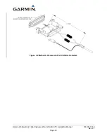
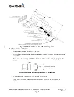
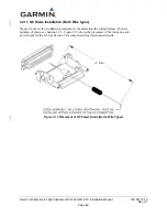
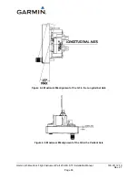
Figure 3-5 CAN Bus Termination for GAD 29/29B
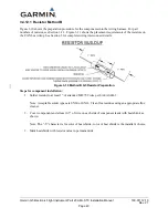
Figure 3-6 CAN Bus Termination for G5 on M27500 Wire
NOTE
For installation of 15Ω resistors on 120Ω CAN cable see Figure 3-8 and Figure 3-9.
Both ends of the CAN bus must have a CAN bus terminator installed (Figure 3-2), but devices that are
not at the ends of the CAN bus should not have a CAN bus terminator installed .
3.4.5.2.4 CAN Bus Installation Guidelines
For maximum reliability of the CAN bus, the following guidelines should be followed:
•
The CAN bus backbone must be a single linear path with exactly two distinct ends. CAN bus
connections should be “daisy chained” from device to device. Avoid “star” and “Y” topologies,
and do not use a hub device (see Figure 3-3).
•
The overall length of the bus should not exceed 85 feet.
•
Do not connect more than one device to the CAN bus backbone at the same point. Instead, daisy
chain the CAN bus backbone from one device to the next.
•
Observe proper wiring, shielding, and grounding requirements as described above.
•
Terminate the CAN bus at the two extreme ends of the bus, as described above.
•
When adding a new device to the CAN bus, evaluate proposed modifications to the CAN bus
wiring connections to ensure compliance with all above requirements.
3.4.5.3 Coaxial Cable Considerations
When routing coaxial cables, observe the following precautions:
•
Avoid sharp bends.
•
Avoid routing cables near power sources (e.g. 400 Hz generators, trim motors, etc.) nor near
power for fluorescent lighting
.
•
For excess coax cable, coil as necessary and use cable ties to secure coil. Do not attempt to
shorten the pre-installed lead on the Glare Shield Mounted GPS Antenna.

