

Garmin G5 Electronic Flight Instrument Part 23 AML STC Installation Manual
190-01112-10
Rev. 21
Page 214
c.
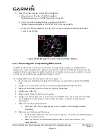
For each VHF NAV radio, monitor one local frequency, one remote (far field) frequency,
and one unused frequency.
d.
Make sure there are no guidance errors.
e.
Make sure there are no audio tones that interfere with the station ID.
f.
For each GPS Navigator, enter a simple flight plan and display as appropriate. i.e.
Navigator Display, G5, HSI, CDI etc., if installed.
g.
Make sure there are no guidance errors.
9.
Make sure all other avionics properly function.
VICTIM
G5
#1
G
5 #2
(I
f i
ns
tal
led)
G
MU 1
1
(If ins
tal
led)
G
AD 29/
2
9B
(If i
ns
tal
led)
G
AD 13
(if i
ns
tal
led)
Magne
ti
c
Compa
s
s
Cl
oc
k
O
AT Indi
c
ator
Power Pl
ant Ins
tr
uments
Auto
pi
lot / S
AS
Nav
igati
on
Radi
o(s)
Comm
uni
c
ati
on Radi
o(s)
Engi
ne Rel
ight
Fuel V
al
v
e
Pi
tot Heat
Pul
s
e Li
ght
G
ene
rator
Pos
Lt
Anti
Col
l Lt
Ldg Lts
G
ov
RPM
Inc
r /
Dec
r
Eng
Dei
c
ing
H
y
d Sy
s
tem
Radar Al
ti
meter
TAS/TCAS
Tr
ans
pond
er
Audi
o Pa
nel
G
TX 3X5
<ad
d equi
pment
here>
<ad
d equi
pment
h
ere>
SOURCE
G5 #1
G5 #2
(If installed)
GMU 11
(If installed)
GAD 29/29B
(If installed)
GAD 13
(if installed)
Magnetic
Compass
Clock
OAT Indicator
Power Plant
Instruments
Autopilot / SAS
Navigation
Radio(s)
Communication
Radio(s)
Engine Relight
Fuel Valve
Pitot Heat
Pulse Light
Generator
Pos Lt
Anti Coll Lt
Ldg Lts
Gov RPM Incr /
Decr
Eng Deicing
Hyd System
Radar Altimeter
TAS/TCAS
Transponder
Audio Panel
GTX 3X5
<add
equipment
here>
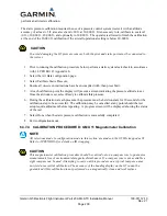
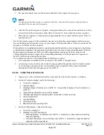
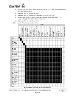
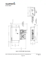
Figure 6-6 Example EMC Source/Victim Matrix


