

G5 Electronic Flight Instrument Pilot's Guide for Non-Certified Aircraft
190-02072-00 Rev. G
13
Flight Instruments
System Overview
Flight Instruments
AFCS
Additional F
eatur
es
Index
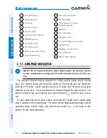
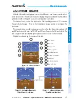
The Airspeed Trend Vector is a vertical, magenta line, extending up or down on the
airspeed scale, shown to the right of the color-coded speed range strip. The end of
the trend vector corresponds to the predicted airspeed in 6 seconds if the current rate
of acceleration is maintained. If the trend vector crosses V
NE
, the text of the actual
airspeed readout changes to yellow. The trend vector is absent if the speed remains
constant or if any data needed to calculate airspeed is not available due to a system
failure.
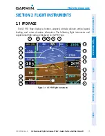
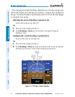
Figure 2-2 Airspeed Indicator
Ground Speed
Actual Airspeed
Airspeed Trend Vector
Airspeed Color Ranges
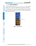
Vspeed References
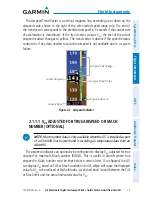
2.1.1.1 V
NE
ADJUSTED FOR TRUE AIRSPEED OR MACH
NUMBER (OPTIONAL)
NOTE:
Mach number data is only available when the G5 is installed as part
of a G3X/G3X Touch system and is receiving air temperature data from an
ADAHRS.
The airspeed indicator can optionally be configured to display V
NE
adjusted for true
airspeed or maximum Mach number (MMO). This is useful in aircraft where true
airspeed or Mach number must be kept below a certain limit. If configured, the G5
can display V
NE
based on TAS or Mach in addition to IAS, which will cause the displayed
value for V
NE
to be reduced at high altitudes. A solid red band is used between the TAS
or Mach limit and the actual indicated value for V
NE
.