background image

1

Complete an action:
• For Windows computers, select the 

Safely Remove 

Hardware

 icon in the system tray, and select your device.

• For Mac computers, drag the volume icon to the trash.

2

Disconnect the cable from your computer.

Appendix

Accessories and Replacement Parts

Purchasing Accessories

Go to 

http://buy.garmin.com

.

Optional Maps

You can use additional maps with the device, such as BirdsEye 

satellite imagery, BlueChart

®

 g2, and City Navigator

®

 detailed 

maps. Detailed maps may contain additional points of interest, 

such as restaurants or marine services. For more information, 

go to 

http://buy.garmin.com

 or contact your Garmin dealer.

ANT+ Sensors

Your device can be used with wireless ANT+ sensors. For more 

information about compatibility and purchasing optional sensors, 

go to 

http://buy.garmin.com

.

tempe

The tempe is an ANT+ wireless temperature sensor. You can 

attach the sensor to a secure strap or loop where it is exposed 

to ambient air, and therefore, provides a consistent source of 

accurate temperature data. You must pair the tempe with your 

device to display temperature data from the tempe.

Using Optional Fitness Accessories

1

Bring the device within range 10 feet (3 m) of the ANT+ 

accessory.

2

Select 

Setup

 > 

ANT Sensors

.

3

Select 

Heart Rate Monitor

Bike Cadence Sensor

, or 

tempe Sensor

.

4

Select 

On

Off

, or 

Search for New

.

5

Customize the data fields to view the heart rate or cadence 

data (

Customizing the Data Fields

, page 12

).

Tips for Pairing ANT+ Accessories with Your Garmin Device

• Verify that the ANT+ accessory is compatible with your 

Garmin device.

• Before you pair the ANT+ accessory with your Garmin 

device, move 10 m (32.9 ft.) away from other ANT+ 

accessories.

• Bring the Garmin device within range 3 m (10 ft.) of the ANT+ 

accessory.

• After you pair the first time, your Garmin device automatically 

recognizes the ANT+ accessory each time it is activated. This 

process occurs automatically when you turn on the Garmin 

device and only takes a few seconds when the accessories 

are activated and functioning correctly.

• When paired, your Garmin device receives data from only 

your accessory, and you can go near other accessories.

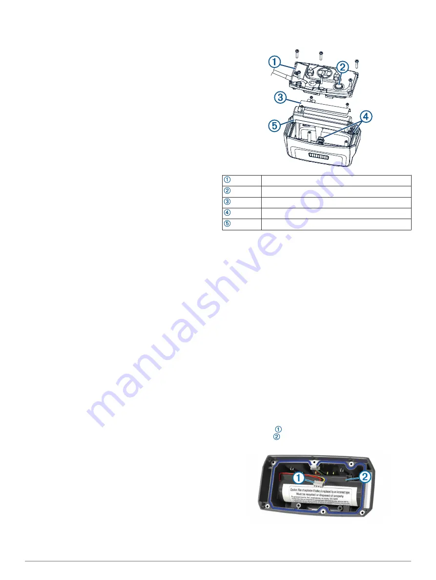
TT15F Battery Replacement Instructions

TT15F Components

Back plate

Power key

Battery cover

Connectors

Battery

Removing the Old Battery

Before you replace the battery, you must remove all dirt, water, 

and debris from the device. You must also have a small Phillips 

screwdriver.

1

Remove the six screws from the outer edges of the back 

plate.

NOTE: 

You should leave the two inner screws in place.

2

Pry off the back plate.

3

Disconnect the battery connector and power connector.

4

Remove the screws that secure the battery cover.

5

Remove the battery cover and the battery.
Remember the orientation of the battery. You must install the 

new battery the same way.

After you remove the old battery, contact your local waste 

disposal department to properly recycle the battery.

Installing the New Battery

Before you replace the battery, you must remove the old battery 

(

Removing the Old Battery

, page 17

). You also must have a 

small Phillips screwdriver. You may need a small flat 

screwdriver.

1

Install the new battery using the same orientation as the old 

battery.
The connector   should face the end nearest the power key, 

and the bump   where the wires connect to the battery 

should face toward the side with the charging clip contacts.

2

Replace the battery cover.

3

Replace the screws to secure the battery cover.

4

Connect the battery connector and power connector.

Appendix

17

Summary of Contents for ALPHA 100F

Page 1: ...ALPHA 100FWITHTT15F TT15FMINI Owner sManual...

Page 2: ...ning the use of this product Garmin the Garmin logo Alpha ANT BlueChart and City Navigator are trademarks of Garmin Ltd or its subsidiaries registered in the USA and other countries BaseCamp TT and te...

Page 3: ...dding a Contact Using MURS VHF 7 Adding a Contact Using a Contact ID 7 Initiating an Emergency Alert 7 Sending a Message to Your Contacts 7 Tracking a Contact 7 Finding Your Contact ID 8 Changing Your...

Page 4: ...tes 14 Updating the Software 14 Device Care 14 Cleaning the Device 14 Cleaning the Touchscreen 14 Specifications 14 Alpha 100F Handheld Device Specifications 14 TT15F Dog Collar Device Specifications...

Page 5: ...ing keys Power key Mounting spine microSD memory card slot under battery Battery cover D ring Mini USB port under weather cap Dog Collar Device NOTE Your dog collar device may look different than the...

Page 6: ...riple blink in green Using the Touchscreen Select to open the application drawer Select to open a menu Select to close the page and return to the previous page If you are more than one menu from the h...

Page 7: ...ar and select The dog s track code allows you to track the dog The dog s train code allows you to both track and train the dog 5 Enter the name of the dog and select OK Finding the Dog ID and Track an...

Page 8: ...that the collar is not too tight 3 Wiggle the device to work the contact points through the dog s coat NOTE The contact points must have contact with the dog s skin to be effective 4 If the strap is t...

Page 9: ...ect the dog 3 Select Show Info Go The map opens 4 Follow the magenta line to the dog 5 If necessary select to track the dog using the dog tracking compass Tracking with BaseCamp BaseStation Before you...

Page 10: ...used as either a positive or negative training cue depending on your training program Vibration Applies vibration instead of stimulation to the dog the entire time you press the training key for a max...

Page 11: ...ands Abandoning the collar too early can lead to problems in the future Contact Tracking You can track other hunters so you know where they are at all times You can also send messages to your contacts...

Page 12: ...Covey 3 Enter the number of birds flushed 4 Enter the number of birds taken 5 Select OK Turning On the Collar Light You can turn on the LEDs on the collar at night to help locate a dog or to warn driv...

Page 13: ...eview To change the order of the points on the route select Move Up or Move Down To insert an additional point on the route select Insert The additional point is inserted before the point you are edit...

Page 14: ...el the icon moves and leaves a track log trail Waypoint names and symbols appear on the map When you are navigating to a destination your route is marked with a magenta line on the map When the map or...

Page 15: ...to display pressure and elevation over time or distance 1 Select Elevation Plot Change Plot Type 2 Select an option Resetting the Elevation Plot Select Elevation Plot Reset Clear Current Track Yes Tri...

Page 16: ...data fields 2 Select a data field to customize 3 Select the new data field For data field descriptions see Data Field Options page 19 Enabling the Map Data Fields Select Setup Map Dashboard Small Data...

Page 17: ...acks Tracks are saved and cleared automatically based on the user setting Color Sets the color of the track line on the map Routing Settings The device calculates routes optimized for the type of acti...

Page 18: ...device or collar software you must connect the handheld device Connecting the Handheld Device to a Computer page 16 or the collar Connecting the Collar to a Computer page 16 to the computer You must u...

Page 19: ...the Map Drawing Speed page 15 1 The device withstands pressure equivalent to a depth of 10 m For more information go to www garmin com waterrating Put the dog collar device into rescue mode Turning On...

Page 20: ...evice 3 Plug the other end of the USB cable into an available USB port on the computer Your device and memory card optional appear as removable drives in My Computer on Windows computers and as mounte...

Page 21: ...ther ANT accessories Bring the Garmin device within range 3 m 10 ft of the ANT accessory After you pair the first time your Garmin device automatically recognizes the ANT accessory each time it is act...

Page 22: ...Replace the back plate and replace and tighten the screws to secure the back plate 15Replace the L shaped cover and replace and tighten the screws to secure the L shaped plate 16Verify the gasket is n...

Page 23: ...raveled to the change in vertical distance Glide Ratio to Dest The glide ratio required to descend from your current position to the destination elevation You must be navigating for this data to appea...

Page 24: ...t at Dest The last point on the route to the destination You must be navigating for this data to appear Waypoint at Next The next point on the route You must be navigating for this data to appear 20 A...

Page 25: ...I icons 5 intensity level choosing 6 K keys 1 training 6 L line of sight radio communication 4 locking screen 2 M main menu customizing 12 maps 8 9 data fields 12 measuring distances 10 navigation 10...

Page 26: ...support garmin com GUID E3F46E61 51AE 4D62 A595 91E3955DFC8C v2 August 2020...

Reviews: