


9 - AUX PAGES
182
190-00357-00 Rev G
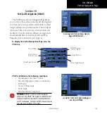
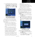
2. Turn the
large right
knob to select the desired
item, and press
ENT
.
...to display the corresponding page (e.g.
Units / Position Page).
The following items are available:
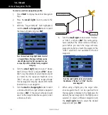
CDI / Alarms
— allows you to define the scale for
the 500W-series unit on-screen course deviation
indicator. The scale values represent full scale
deflection for the CDI to either side. The default
setting is “Auto”. At this setting, the CDI scale is
set to 2.0 NM during the “en route” phase of flight.
Within 31 NM of your destination airport, the CDI
scale gradually ramps down to 1.0 NM (termi-
nal area). Likewise, when leaving your departure
airport the CDI scale is set to 1.0 NM and gradu-
ally ramps up to 2 NM beyond 30 NM (from the
departure airport). During approach operations
the CDI scale gradually transitions down to an
angular CDI scale. At 2.0 NM of the final approach
fix (FAF), CDI scaling is tightened from 1.0 to the
angular full scale deflection (typically the angular
full-scale deflection is 2.0°, but will be as defined
for the approach).
CDI / Alarms Page
If a lower CDI scale setting is selected (i.e., 1.0 or
0.3 NM), the higher scale settings are not selected
during ANY phase of flight. For example, if 1.0 NM
is selected, the 500W-series unit uses this for en
route and terminal phases and ramps down further
during an approach. Note that the Horizontal
Alarm (HAL) protection limits listed below follow
the selected CDI scale, unless corresponding flight
phases call for lower HAL. For example, if the 1.0
NM CDI setting is selected, full-scale deflection
during approach will still follow the approach CDI
scale settings.
CDI Scale
Horizontal Alarm
Limit
Auto (oceanic)
2.0 NM
±2.0 NM or Auto (en route)
2.0 NM
±1.0 NM or Auto (terminal)
1.0 NM
±0.3 NM or Auto
(approach)
0.3 NM
An “auto” ILS CDI selection allows the 500W-
series unit to automatically switch the external CDI
from the GPS receiver to the VLOC receiver, when
intercepting the final approach course. Or, select
“manual” to manually switch the external CDI
connection, as needed (using the
CDI
key). If the
unit is installed with a KAP140/KFC225 autopilot,
Setup 1 Page
Summary of Contents for 500W Series
Page 1: ...500W Series Pilot s Guide Reference ...
Page 10: ...INTRODUCTION viii 190 00357 00 Rev G Blank Page ...
Page 68: ...2 NAV PAGES 58 190 00357 00 Rev G Blank Page ...
Page 92: ...4 FLIGHT PLANS 82 190 00357 00 Rev G Blank Page ...
Page 158: ...6 WPT PAGES 148 190 00357 00 Rev G Blank Page ...
Page 234: ...APPENDIX D Index 224 190 00357 00 Rev G Blank Page ...
Page 235: ......


