Installation Instructions for
“Out of Sight” Ladders
Form 12.105
ASSEMBLY INFORMATION
1. Check parts against parts list.
2. Read Instructions completely before starting assembly.
3. NOTE: This product uses locknuts for a secure assembly.
Locknuts thread on harder than conventional nuts and
require a screwdriver and wrench for attachment.
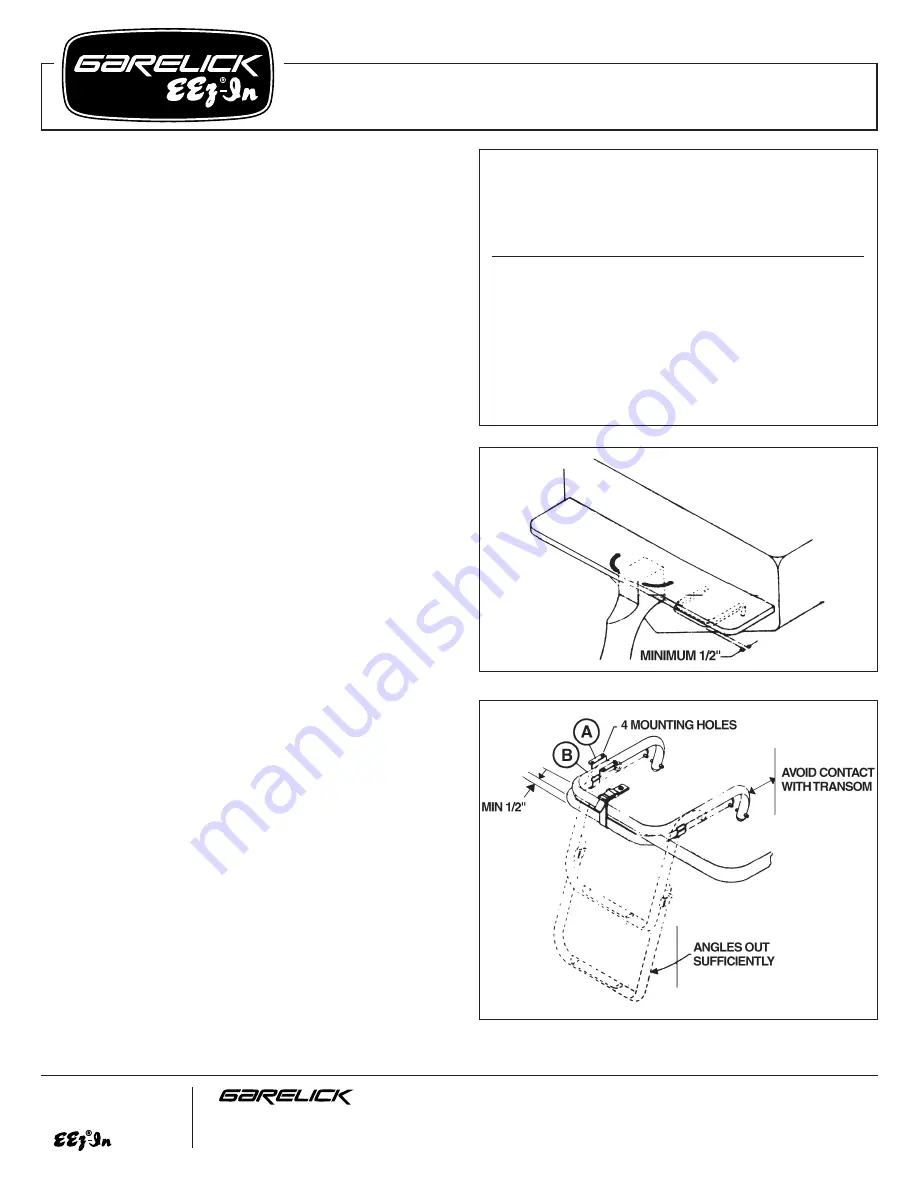
Refer to Fig. 1
1. Choose the most suitable side of your transom platform
for mounting the ladder. When mounting, locate a place
where the ladder will not interfere with the turning of the
motor or be excessively close to the propeller of your
boat.
2. Place the ladder under the deck where it will be mounted.
Make sure the area is flat and has enough space to
facilitate proper operation. Position it so that when stowed
it will protrude a minimum of 1/2" from the deck. Mark
this general area.
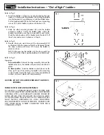
Refer to Fig. 2
3. Slide one mounting bracket (A) onto the main ladder
vertical as shown. Make sure it touches the slide bracket
(B), this will insure the ladder will store exactly as
positioned. NOTE: Slide bracket (B) is only supplied on 2
& 3 step model ladders.
4. Position the mounting bracket (A) with the ladder in the
area to be mounted as determined in Step 2. Mark the
bracket’s four mounting holes onto the deck surface.
Check the operation of the ladder before drilling the holes
for the following: A) When in “up” position, ladder is
stowed without hitting the transom. B) When in “down”
position, the ladder will angle out sufficiently for easy
ascent. C) The ladder will slide out; there is no deck trim
or moulding that will impede its operation. If this occurs,
make a shim under the mounting brackets that will bring
the ladder down far enough for proper operation.*
5. Drill the four marked holes with 5/16" drill bit. NOTE: It
is recommended to through bolt this ladder for best
results.
*NOTE: This might be necessary for pontoon boat installations.
Parts List
“Out of Sight” Ladder
Ref. Factory
No.
Letter
Part No.
Req.
Description
A
50.394
2
Large mounting bracket
C
06.135
2
Poly sleeve
D
50.392
2
Backing plate
E
03.085
8
1
⁄
4
-20 x 2
1
⁄
4
" machine screw
F
03.221
8
1
⁄
4
-20 locknut
G
06.038
1
Securing strap
H
03.114
1
#8x1" s.s. screw
FIG. 1
FIG. 2
Write for
a Complete
Catalog
Phone: 651-459-9795
PO Box 8, 644 2nd Street
E-mail: [email protected]
St. Paul Park, Minnesota 55071
On the Web: www.garelick.com
3/98
(over)


