l
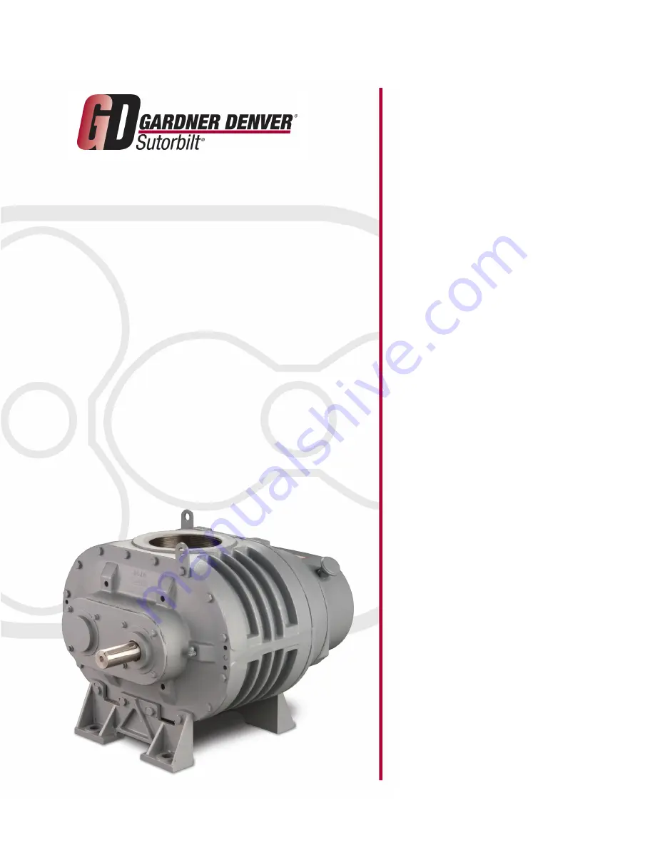
PARTS LIST OPERATING AND SERVICE MANUAL
LEGEND
“P” SERIES BLOWERS
2” – 5” GEAR DIAMETER
Models GAA_ _ P _ GAB_ _ P _ GAC_ _ P _ GAE_ _ P _
SB-7-621 Version 06 April 2, 2007
Page 1: ...l PARTS LIST OPERATING AND SERVICE MANUAL LEGEND P SERIES BLOWERS 2 5 GEAR DIAMETER Models GAA_ _ P _ GAB_ _ P _ GAC_ _ P _ GAE_ _ P _ SB 7 621 Version 06 April 2 2007 ...
Page 2: ......
Page 3: ...respond and assist you by providing fast expert maintenance and repair service INSTRUCTIONS FOR DETERMINING BLOWER CONFIGURATION 1 Face the blower drive shaft 2 In a VERTICAL configuration air flow is horizontal 3 In a HORIZONTAL configuration air flow is vertical 4 In a vertical configuration a BOTTOM HAND exists when the drive shaft is below the horizontal center line of the blower A TOP HAND ex...
Page 4: ...G23 Case 12Quarts 28G24 1 Gallon Container 28G40 5 Gallon Pail 28G25 55 Gallon Drum 28G28 AEON PD Food Grade Synthetic Lubricant Description Part Number 1 Quart 28H97 Case 12Quarts 28H98 1 Gallon Container 28H333 5 Gallon Pail 28H99 55 Gallon Drum 28H100 Drive End AEON PD Grease Description Part Number Case 10 Tubes 28H283 Call your local Sutorbilt Distributor to place your order for Gardner Denve...
Page 5: ... economical operation and minimum downtime Danger is used to indicate the presence of a hazard which will cause severe personal injury death or substantial property damage if the warning is ignored Warning is used to indicate the presence of a hazard which can cause severe personal injury death or substantial property damage if the warning is ignored Caution is used to indicate the presence of a h...
Page 6: ...ved Electrical shock can and may be fatal Blower unit must be grounded in accordance with the National Electrical Code A ground jumper equal to the size of the equipment ground conductor must be used to connect the blower motor base to the unit base Open main disconnect switch tag and lockout before working on the control Disconnect the blower from its power source tag and lockout before working o...
Page 7: ...utions 5 Sutorbilt Legend Series Blowers Matrix Menu 8 Introduction 9 Section 1 Equipment Check 10 Section 2 Installation 12 Section 3 Lubrication 17 Section 4 Operation 20 Section 5 Special Tools Required 23 Section 6 Disassembly Instructions 25 Section 7 Assembly Instructions 28 Section 8 Parts List 35 ...
Page 8: ...equired Section 5 23 Storage 10 Trouble Shooting 22 Warranty 44 LIST OF ILLUSTRATIONS FIGURE 2 1 BLOWER MOUNTING CONFIGURATION 13 FIGURE 2 2 BELT DRIVE OVERHUNG LOAD CALCULATIONS 15 FIGURE 3 1 LUBRICATION 17 FIGURE 3 2 APPROXIMATE OIL CAPACITIES 18 FIGURE 3 3 AEON PD SYNTHETIC LUBRICANT 18 FIGURE 3 4 LUBRICATION RECOMMENDATION 19 FIGURE 4 1 MAXIMUM OPERATING LIMITATIONS 20 FIGURE 5 1 PULLER PLATE ...
Page 9: ...ED IN TO FIND THE APPROPRICATE CONSTRUCTION OPTION WITH WHICH YOUR MACHINE IS EQUIPPED COLUMN 1 BASIC DESIGNATOR COLUMN 2 PRODUCT FAMILY COLUMN 3 GEAR DIAMETER A 2 E 5 H 8 B 3 F 6 C 4 G 7 COLUMN 4 CASE LENGTH L Low Pressure M Medium Pressure H High Pressure COLUMN 5 CONFIGURATION A Vertical Top Hand Central Timed B Vertical Bottom Hand Central Timed C Horizontal Left Hand Central Timed D Horizonta...
Page 10: ... with other precision machinery there are several relatively simple installation operation and maintenance procedures that you must observe to assure optimum blower performance There is no guesswork in the manufacture of your highly advanced Sutorbilt blower and there must be none in preparing the blower to get the job done in the field The purpose of this manual is to help you properly install op...
Page 11: ...tore the blower in a clean dry heated if possible area 2 Make certain inlet and discharge air ports are tightly covered to prevent foreign material from entering the air box 3 All exposed non painted surfaces should be protected against rust and corrosion 4 Provide adequate protection to avoid accidental mechanical damage 5 In high humidity or corrosive environments additional measures may be requ...
Page 12: ... discharge connections are in the vertical position vertical airflow On vertically mounted units it will be necessary to lay the unit on its side supporting the ends of the unit so as not to restrict the port on the bottom side Place a shallow pan on the under side of the unit With the blower disconnected from power spray the solvent in the top port rotating the impellers by spinning the shaft man...
Page 13: ... and wedges removed before final tightening of anchor bolts Refer to grouting instructions Where a concrete foundation is not feasible care must be taken to insure that equipment is firmly anchored to adequate structural members restricting movement and vibration MOUNTING CONFIGURATIONS The blower flex mount design enables horizontal and vertical mounting configurations with top or bottom hand rig...
Page 14: ...Motor and blower pulleys must be parallel to each other and in the same plane within 1 32 inch Belt tension should be carefully adjusted to the belt manufacturer s recommendation using a belt tension gauge Check tension frequently during the first day of operation Over tightening belts leads to heavy bearing loads and premature failure On the direct connected units alignment and lubrication of cou...
Page 15: ...t Figure 2 2 page 15 2 Insert the calculated belt pull into the formula for Calculation of Shaft Moment FIGURE 2 2 page 15 to arrive at the calculated shaft moment PIPING Inlet and discharge connections on all blowers are large enough to handle maximum volume with minimum friction loss Reducing the pipe diameter on either inlet or discharge will only create additional line loss and increase the ov...
Page 16: ...625 0 904 0 875 0 852 1 125 0 789 1 375 0 706 0 150 0 980 0 400 0 943 0 650 0 899 0 900 0 847 1 150 0 782 1 400 0 697 0 175 0 977 0 425 0 939 0 675 0 894 0 925 0 841 1 175 0 774 1 425 0 687 0 200 0 973 0 450 0 935 0 700 0 889 0 950 0 835 1 200 0 767 0 225 0 969 0 475 0 930 0 725 0 884 0 975 0 829 1 225 0 759 ARC OF CONTACT FACTORS Belt Pull 2 5 Ac X 125954 x Hp x S F Ac D x RPM Key Ac Arc of Conta...
Page 17: ...ement has been used It will also eliminate both premature filter servicing and premature blower failure due to a plugged filter when the filter pressure drop is used to establish maintenance points In all cases refer to the filter manufacturer s service instructions Due to the many types of filters it is not practical to give specific instructions covering all models NOTICE No matter what type of ...
Page 18: ... rust inhibitors and be suitable for blower discharge temperatures up to 350 F 177 C Completely clean or purge the factory filled grease from the blower Do not mix different types of grease as they may not be compatible Substitutions may cause early bearing failure Re grease bearings every 500 hours of operation Lubricate each bearing through the grease fittings located at C in FIGURE 3 1 2 places...
Page 19: ... Food Grade Lubricant Description Part Number 1 Quart 28H97 Case 12 Quarts 28H98 1 Gallon Container 28H333 5 Gallon Pail 28H99 55 Gallon Drum 28H100 FIGURE 3 3 AEON PD SYNTHETIC LUBRICANT NOTICE Machines are shipped without oil in the sump Do not operate before adding lubricant LUBRICATION INSTRUCTIONS Filling Procedure For 2 and 3 sizes Refer to FIGURE 3 1 page 17 Remove the oil level plug H and ...
Page 20: ... new lubricant Fill to normal level of the blower which is at the middle of the sight glass when the machine is not operating Run the blower for one hour Shut off the blower and drain the lubricant completely Refill the blower again with the new lubricant Ambient Temperature Blower Discharge Temperature Less than 10 F 10 F to 32 F 32 F to 90 F Greater than 90 F Less than 32 F 0 C ISO 100 ISO 100 3...
Page 21: ...essure differential rating of the blower NOTICE Relief valves should be placed as close as possible to the blower inlet or discharge In some instances pressure may be relieved at a lower point than the blower maximum in order to protect the motor or the equipment served by the blower Discharge temperature switches are recommended to protect against excessive inlet restriction or inlet temperatures...
Page 22: ...and incidental contact 5 Check the unit for proper lubrication Proper oil level cannot be over emphasized Too little oil will ruin bearings and gears Too much oil will cause overheating and can ruin gears and cause other damage Insure that grease lubricated bearings are properly lubricated 6 With motor electrical power locked out and disconnected turn the drive shaft by hand to be certain the impe...
Page 23: ...ure differential 4 Worn gears 5 Worn bearings 1 Re time impellers 2 Check mounting alignment and relieve pipe strains 3 Reduce to manufacturer s recommended pressure Examine relief valve re set if necessary 4 Replace timing gears 5 Replace bearings Excessive blower temperature 1 Too much oil in gear case 2 Too low operating speed 3 Dirty air Filter 4 Clogged filter or muffler 5 Excessive pressure ...
Page 24: ...ECTION 5 MAINTENANCE ORDER SPECIAL TOOLS BY PART NUMBER SEE PAGE 1 FOR ORDERING INSTRUCTIONS Unit Size Part Number 2 200GAA340 3 201GAA340 4 202GAA340 5 203GAA340 FIGURE 5 1 PULLER PLATE FIGURE 5 2 GEAR DRIVER 208GAA074 ...
Page 25: ... Part Number 2 204GAA074 3 205GAA074 4 206GAA074 5 207GAA074 FIGURE 5 3 MECHANICAL SEAL INSTALLATION TOOL Unit Size Part Number 2 200GAA074 3 201GAA074 4 202GAA074 5 203GAA074 FIGURE 5 4 BEARING PRESS TOOL MECHANICAL SEAL UNITS ...
Page 26: ...CAN BE REASSEMBLED IN THE SAMEPOSITION IMPELLERS HEADPLATES AND GEARS 4 If the timing gears appear undamaged the gear backlash must be checked to see if the gears can be salvaged A Mount a magnetic base dial indicator on the gear headplate see FIGURE 6 1 B Lock one impeller stationary by wedging a feeler gauge between the impeller and the headplate C The tip of the indicator should be placed at th...
Page 27: ...adplates should also be matchmarked to facilitate blower reassembly 6 Using a gear puller remove timing gears The taper pin should back out with the gear as the gear is being removed see FIGURE 6 3 Use caution not to damage gear teeth with puller if gears are to be used again NOTICE Blowers with mechanical seals have two wavy washers 28 located between the bearings and the cover on the drive end 7...
Page 28: ...place grease seals each time the headplate is removed NOTICE Seals and bearings should be replaced during overhaul as a matter of service policy FIGURE 6 6 14 Remove the four cap screws 10 which fasten the bearing retainers 12 to the gear headplate 15 Attach puller plate to the gear headplate using the tapped holes used to secure the bearing retainers 16 Install a gear puller to one of the shafts ...
Page 29: ...he headplate is removed NOTICE Make sure seals are fully seated Use extreme care when installing MECHANICAL SEALS ONLY A Lightly coat the headplate bores with assembly lubricant B Refer to Figure 7 1 Install mechanical seal A into the headplate bore C using a press and the correct driver shown on page 24 Drive the seal securely on to its seat Use extreme care when installing seals in the headplate...
Page 30: ...r the unit to set level Measure the total end clearance using a depth micrometer see Figure 7 2 NOTICE If more than 007 shim is required put 007 on the drive end and the remaining on the gear end If total clearance is not within the limits specified in Figure 7 4 page 30 it may be necessary to shim the case to obtain the proper total end clearance The shim should be placed between the drive headpl...
Page 31: ...with a light oil as described previously Install gear end bearings 14 as far as possible without force Use the plate used to install the drive end bearings to press the bearings on the shafts as described in Step 8 Press bearings into the gear headplate until completely seated in the bearing bore NOTICE Bearings will not be flush with gear headplate bores when completely seated 10 Impellers should...
Page 32: ...oth impellers This will stop the impellers from contacting the headplate while the gears are being driven on FIGURE 7 5 If installing gears on a blower containing mechanical seals a press must be used to drive the gears on the shafts Blows from a hammer or mallet will damage the seal C Secure the bearing retainer plate 12 to the gear headplate using capscrews 10 Refer to FIGURE 7 8 page 34 for tor...
Page 33: ... C C within 001 inch Clearances must be checked on both sides of each impeller lobe over the entire length This procedure may require repeating several times until the impeller lobe clearance is equal on both sides NOTICE The gear used for adjustment should be flush with its mate on completion of the timing J Check gear backlash four places at 90 degree intervals as described in the disassembly pr...
Page 34: ...H and the bearing inner race E keeps the shaft from moving axially End clearance adjustment is by movement of the bearing retainer K Tightening the bearing retainer screws M moves the bearing to load the wavy spring J and the impeller is forced toward the drive end Relaxing the screws allows the wavy spring to return the impeller toward the gear end A Assemble drive cover to drive headplate Refer ...
Page 35: ... evenly Refer to FIGURE 7 8 for torque specifications 18 Place the blower on its feet on a flat surface Loosen cap screws 16 and level the unit up The bench or blower base flatness should be within 002 of an inch Re tighten cap screws 16 to the specification in FIGURE 7 8 NOTICE If the unit is not flat within 002 of an inch it will be necessary to shim the blower feet at installation GEAR DIAMETER...
Page 36: ...SB 7 621 Page 35 SECTION 8 PARTS LIST 300GAA810 C Ref Drawing ...
Page 37: ... 900894021001 900894021001 MECHANICAL SEAL 1 204GAA006 204GAA006 19 DOWEL PIN 4 62M48 62M48 20 LIFTING LUG 2 200GAA451 200GAA451 21 SCREW BEARING HOUSINGS TO IMPELLER CASE 14 75A34 75A34 22 IMPELLER CASE 1 900894021201 900894021401 23 SHAFT ASSEMBLY GROUP SEAL VENTS 1 GAA81899 GAA81898 SHAFT ASSEMBLY GROUP CONSISTS OF 1 ASSEMBLY SHAFT LONG 1 ASSEMBLY SHAFT SHORT 24 HOUSING BEARING DRIVE LIP SEAL 1...
Page 38: ...SB 7 621 Page 37 200GAB810 E Ref Drawing ...
Page 39: ...IN 4 62M48 62M48 62M48 20 LIFTING LUG 2 200GAA451 200GAA451 200GAA451 21 SCREW BEARING HOUSINGS TO IMPELLER CASE 16 655ED040 655ED040 655ED040 22 IMPELLER CASE 1 900873034301 900873033801 900873034201 23 SHAFT ASSEMBLY GROUP 1 GAB81905 GAB81907 GAB81906 SHAFT ASSEMBLY GROUP CONSISTS OF 1 ASSEMBLY SHAFT LONG 1 ASSEMBLY SHAFT SHORT 24 HOUSING BEARING DRIVE END LIP SEAL 1 900873033501 900873033501 90...
Page 40: ...SB 7 621 Page 39 300GAC810 B Ref Drawing ...
Page 41: ...62M48 20 LIFTING LUG 2 200GAA451 200GAA451 200GAA451 21 SCREW BEARING HOUSINGS TO IMPELLER CASE 16 655ED040 655ED040 655ED040 22 IMPELLER CASE 1 900883042201 900883041801 900883042001 23 SHAFT ASSEMBLY GROUP 1 208GAC4028 207GAC4028 206GAC4028 SHAFT ASSEMBLY GROUP CONSISTS OF 1 ASSEMBLY SHAFT LONG 1 ASSEMBLY SHAFT SHORT 24 HOUSING BEARING DRIVE END LIP SEAL 1 300GAC006 300GAC006 300GAC006 MECHANICA...
Page 42: ...SB 7 621 Page 41 300GAC810 B Ref Drawing ...
Page 43: ...DOWEL PIN 4 62M48 62M48 62M48 20 LIFTING LUG 2 200GAA451 200GAA451 200GAA451 21 SCREW BEARING HOUSINGS TO IMPELLER CASE 24 655ED040 655ED040 655ED040 22 IMPELLER CASE 1 900883051701 900883051801 900883051901 23 SHAFT ASSEMBLY GROUP 1 207GAE4028 206GAE4028 205GAE4028 SHAFT ASSEMBLY GROUP CONSISTS OF 1 ASSEMBLY SHAFT LONG 1 ASSEMBLY SHAFT SHORT 24 HOUSING BEARING DRIVE END LIP SEAL 1 206GAE006 206GA...
Page 44: ...SB 7 621 Page 43 ...
Page 45: ...tive or Gardner Denver 1800 Gardner Expressway Quincy IL 62305 Customer Service Department Telephone 800 682 9868 Fax 217 221 8780 Sales and Service in all major cities www gardnerdenver com pd blowers gardnerdenver com 2007 Gardner Denver Inc Litho in U S A ...
Page 46: ...is document was created with Win2PDF available at http www win2pdf com The unregistered version of Win2PDF is for evaluation or non commercial use only This page will not be added after purchasing Win2PDF ...