background image

Installation

G&D VisionXS-IP-C-DP-UHR · 

10

English

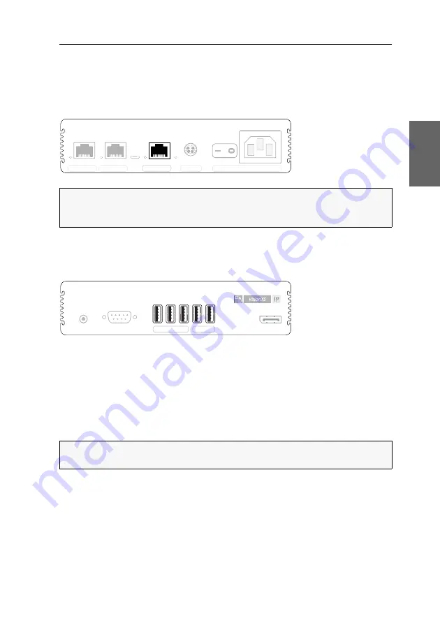
Installing user modules

The remote console is connected to the 

VisionXS-IP-CON

 user module. The computer 

connected to the computer module can be operated from this console.

Establishing a connection to a local management network

Network: 

Insert a category 5 twisted pair cable (or better), which is available as acces-

sory. Connect the other end of the cable to the local network.

Connecting keyboard and mouse of consoles

Keyb./Mouse: 

Connect the mouse and/or the keyboard of the console to this interface.

Generic: 

In the default settings, you can connect additional USB input devices, USB


mass storage devices, and/or a supported display or tablet to this interface.

Activate the 

generic USB

 mode (see 

(De)Activating an USB keyboard or the »Generic USB« 

mode

 on page 41) if you want to connect another USB input device or USB mass 

storage device. In this mode, any data of the USB device is 

not altered

 when transmitted 

to the computer module.

NOTE: 

If desired, connect this network interface to a local network. This enables 

you to access the 

Config Panel

 web application from this network and to send sys-

log messages to this network.

IMPORTANT: 

If the 

generic USB

 mode is active, the OSD cannot be operated by a 

keyboard connected to the 

Generic

 socket.

Service

Transmission 2

Transmission 1

Pwr Main Power

Red. Power

Network

Pwr Main Power

Red. Power

Service

Transmission 2

Transmission 1

Line Out

Serial

DP Out

Generic

Keyb./Mouse

Line Out

Serial

DP Out

Summary of Contents for VisionXS-IP-C-DP-UHR

Page 1: ...Guntermann Drunck GmbH www gdsys de G D VisionXS IP C DP UHR A9100386 1 00 Installation und Bedienung DE EN Installation and Operation...

Page 2: ...chluss G D bernimmt keine Gew hrleistung f r Ger te die nicht bestimmungsgem eingesetzt wurden nicht autorisiert repariert oder modifiziert wurden schwere u ere Besch digungen aufweisen welche nicht b...

Page 3: ...utzt Hochfrequenzenergie und kann diese ausstrahlen Wenn es nicht gem der Anleitung installiert wird kann es Funkst rungen ver ursachen Es wird jedoch keinerlei Garantie daf r bernommen dass die St ru...

Page 4: ...7 Konfiguration der globalen Netzwerkeinstellungen 17 Konfiguration der KVM over IP Verbindung 18 KVM over IP Verbindung des Arbeitsplatzmoduls konfigurieren 19 Konfiguration der Netzwerkschnittstelle...

Page 5: ...out f r Eingaben innerhalb des OSDs ausw hlen 47 Wiederherstellung der Standardeinstellungen 48 Reset der Netzfilterregeln 49 Farbe der Informationseinblendung ndern 50 Anzeige der Informationseinblen...

Page 6: ...uellen getrennt ist Ziehen Sie alle Netzstecker und alle Spannungsversorgungen am Ger t ab Disconnect all power sources Before installation ensure that the device has been disconnected from all power...

Page 7: ...nden der elektrischen Sicherheit ist bei Ger ten mit L ftungs ffnungen nur eine aufrechte horizontale Einbauweise zul ssig Stolperfallen vermeiden Vermeiden Sie bei der Verlegung der Kabel Stolperfal...

Page 8: ...rauchte Batterien d rfen nicht in den Hausm ll geworfen werden Beachten Sie die g ltigen Vorschriften zur Entsorgung elektronischer Produkte CAUTION Risk of explosion if the battery is replaced by an...

Page 9: ...er Matrixswitch Module Sie k nnen die Module wahlweise als Extender oder Matrixswitch Module ver wenden Extender Module Konfigurieren Sie eine KVM over IP Verbindung zwischen dem Rechner und dem Arbei...

Page 10: ...n auf Seite 22 Bei Beachtung der max L nge von Teilstrecken zwischen zwei aktiven Netzwerk komponenten jeweils bis zu 100 Meter ist die gesamte bertragungsl nge unbe schr nkt Lieferumfang Standardlief...

Page 11: ...twahl der Ger te sicher dass die zul ssige Umgebungstemperatur siehe Technische Daten auf Seite 59 in der unmittelbaren N he eingehalten und nicht durch andere Ger te beeinflusst wird WICHTIG Bei Ger...

Page 12: ...es Rechners mit dieser Schnittstelle Ver wenden Sie hierzu das Kabel DP Cable M M 2 HINWEIS Alle Ger tevarianten der VisionXS IP Serie k nnen mit einer externen Spannungsversorgung an der Power Schnit...

Page 13: ...abels ist mit dem Gigabit Ethernet zu verbinden HINWEIS Die Audio Daten werden in der Standardeinstellung des KVM Exten ders zwischen den Switches bertragen Zus tzlich k nnen Sie im OSD die bertragung...

Page 14: ...erreicht HINWEIS Alle Ger tevarianten der VisionXS IP Serie k nnen mit einer externen Spannungsversorgung an der Power Schnittstelle bei Desktop Geh usen Main Power betrieben werden Die Abbildungen in...

Page 15: ...Massenspeicherger te und oder ein unterst tztes Display bzw Tablet anschlie en Aktivieren Sie den Generic USB Modus siehe USB Tastaturmodus oder Generic USB de aktivieren auf Seite 41 wenn Sie ein an...

Page 16: ...hes Twisted Pair Kabel der Kategorie 6 oder h her ein Das andere Ende des Kabels ist mit dem Gigabit Ethernet zu verbinden HINWEIS Die Freischaltung des kostenpflichtig erh ltlichen Transm Redundancy...

Page 17: ...tes erreicht HINWEIS Alle Ger tevarianten der VisionXS IP Serie k nnen mit einer externen Spannungsversorgung an der Power Schnittstelle bei Desktop Geh usen Main Power betrieben werden Die Abbildung...

Page 18: ...zustand des Moduls Weitere Hinweise hierzu erhalten Sie im Kapitel Statusanzeigen ab Seite 58 On Screen Display des Arbeitsplatzmoduls Beim Start des Arbeitsplatzmoduls werden Informationen ber den St...

Page 19: ...rbeitsplatzmoduls aufgeschaltet werden So schalten Sie ein bestimmtes Remote Target auf 1 Starten Sie das lokale On Screen Display mit dem Hotkey Alt Num Standard 2 W hlen Sie im Auswahl Men das aufzu...

Page 20: ...ach der Inbetriebnahme anpassen Die IP Adressen und die KVM over IP Einstellungen sind wie folgt vorkonfiguriert WICHTIG Wenn Sie den KVM Extender als Matrixswitch Endger t mit dem IP Matrixswitch Con...

Page 21: ...dresse des Rechnermoduls Host sowie die Angabe des Control Ports des Rechnermoduls erforderlich Die Konfiguration der Communication Ports und Data Ports werden automatisch zwi schen beiden Modulen aus...

Page 22: ...ellungen stellen auch in komplexen Netzwerken sicher dass der KVM Extender aus allen Teilnetzwerken erreichbar ist So konfigurieren Sie die globalen Netzwerkeinstellungen 1 Verwenden Sie den Remote Ho...

Page 23: ...stellungen folgende Daten 4 Bet tigen Sie die F2 Taste zur Speicherung der durchgef hrten nderungen Globale Einstellungen Bet tigen Sie die F8 Taste zur Auswahl des Betriebsmodus Static Verwendung von...

Page 24: ...M Extender aus allen Teilnetzwerken erreichbar ist So konfigurieren Sie die globalen Netzwerkeinstellungen 1 Verwenden Sie den lokalen Hotkey Alt Num zum Aufruf des Arbeitsplatzmodul OSD 2 Bet tigen S...

Page 25: ...ng und bet tigen Sie die Eingabetaste 4 Erfassen Sie im Abschnitt Lokal folgende Daten 5 Bet tigen Sie die F2 Taste zur Speicherung der durchgef hrten nderungen Globale Einstellungen Bet tigen Sie die...

Page 26: ...alen Hotkey Alt Num zum Aufruf des Arbeitsplatzmodul OSD 2 Bet tigen Sie F11 zum Aufruf des Konfiguration Men s 3 W hlen Sie die Zeile KVM Verbindung und bet tigen Sie die Eingabetaste 4 W hlen Sie di...

Page 27: ...rbindung Bandbreite limitieren In der Standardeinstellung verwendet der KVM Extender die maximal zur Verf gung stehende Bandbreite des Gigabit Ethernets Mittels manuellem Bandbreiten Management k nnen...

Page 28: ...rdaten Communication Datenpa kete sowie die IP Pakete der Video Audio und RS232 Daten Data Datenpakete k nnen Sie je einen DSCP festlegen So konfigurieren Sie die DSCPs der IP Datenpakete 1 Verwenden...

Page 29: ...en und alternativ die bertragung der Audio Daten deaktivieren So de aktivieren Sie die bertragung des Audio bzw RS232 Signals 1 Verwenden Sie den Remote Hotkey Strg Num zum Aufruf des Rechnermodul OSD...

Page 30: ...tellungen und Verweise auf die ausf hrlichen Erl uterungen der Funktionen aufgef hrt Funktion Standardeinstellung Seite nderung des Hotkeys Strg 31 nderung der OSD Taste Num 32 On Screen Display mit d...

Page 31: ...n Displays am Arbeitsplatz So starten Sie das On Screen Display 1 Starten Sie das On Screen Display mit dem Hotkey Strg Num Standard Funktion Standardeinstellung Seite Farbe der Informationseinblendun...

Page 32: ...ezeigt Listenfeld Im Listenfeld werden die Men eintr ge des ausgew hlten Men s aufgef hrt Zu unterscheiden sind zwei Arten von Men eintr gen Men punkte mit Untermen Diese Eintr ge werden mit drei Punk...

Page 33: ...Men ansicht und zeigt das bergeordnete Men an Falls Eingaben ge ndert aber nicht gespeichert wurden erhal ten Sie diesbez glich eine Meldung Tabulatortaste Verwenden Sie diese Taste um die Positionsma...

Page 34: ...auf das Sprachk rzel der aktuellen Sprache rechts oben 2 Schalten Sie die zu verwendende Sprache mit einem Klick auf die gew nschte Sprache um HINWEIS Grundlegende Informationen zu den Systemvorausset...

Page 35: ...der Webapplikation So beenden Sie die Webapplikation 1 Klicken Sie auf das Benutzersymbol rechts oben 2 Klicken Sie auf Abmelden um die aktive Sitzung zu beenden WICHTIG Verwenden Sie immer die Abmeld...

Page 36: ...Eingabetaste 3 W hlen Sie die Zeile Hotkeys und bet tigen Sie die Eingabetaste 4 W hlen Sie im Abschnitt Modifizierer mindestens eine der aufgef hrten Hot key Modifizierertasten durch Markierung des...

Page 37: ...onstaste durch Bet tigung der F8 Taste eine OSD Taste aus welche gemeinsam mit der bzw den Hotkey Modifizierer taste n den Aufruf des On Screen Displays bewirkt Num Num Taste Standard Pause Pause Tast...

Page 38: ...Alt Taste Alt Gr OSD Aufruf mit doppeltem Druck auf die Alt Gr Taste Win OSD Aufruf mit doppeltem Druck auf die Windows Taste Shift OSD Aufruf mit doppeltem Druck auf die Umschalt Taste Drucken OSD A...

Page 39: ...hnittstellen des Arbeits platz und des Rechnermoduls erforderlich OSD 1 Starten Sie das On Screen Display mit dem Hotkey Strg Num Standard 2 W hlen Sie die Zeile Arbeitsplatzeinrichtung und bet tigen...

Page 40: ...32 Schnittstelle des Rechnermoduls einstellen m chten Klicken Sie auf den Reiter CON falls Sie den Betriebsmodus der RS232 Schnittstelle des Arbeitsplatzmoduls einstellen m chten 5 W hlen Sie im Feld...

Page 41: ...f hrliche Informationen hierzu finden Sie im separaten Handbuch zur Webapplikation Config Panel So w hlen Sie den EDID Modus des KVM Extenders HINWEIS Beachten Sie bei der Erstinbetriebnahme sowie bei...

Page 42: ...n Reiter Videokan le 4 Klicken Sie bei Einsatz eines Multichannel Ger tes auf den gew nschten Videokanal und anschlie end auf Konfiguration 5 W hlen Sie im Feld EDID Profil des Abschnitts Videokanal z...

Page 43: ...ich zu signalisieren wird das zuletzt empfan gene Bild wahlweise mit einem farbigen Rahmen und oder der Einblendung Frozen und der vergangenen Zeit seit dem Verbindungsabbruch dargestellt Config Panel...

Page 44: ...ungsabbruch Rahmen OSD Anzeige des farbigen Rahmens frame und Einblendung des Hinweises Eingefroren OSD 5 Bet tigen Sie die F2 Taste zur Speicherung der durchgef hrten nderungen Config Panel 1 Klicken...

Page 45: ...eingestellen 3 W hlen Sie in der Zeile DDC CI Unterst tzung durch Bet tigung der F8 Taste zwischen folgenden Optionen aus Die bertragung von DDC CI Signalen ist deaktiviert Standard CPU Monitor Die b...

Page 46: ...en Die folgende Tabelle listet die unterst tzten USB Tastaturen auf Displays und Tablets Sie k nnen den am KVM Extender angeschlossenen Rechner mit einem der unterst tzten Displays oder Tablets bedien...

Page 47: ...r Generic USB Modus unterst tzt viele der am Markt erh ltlichen USB Massenspeicherger te und Eingabeger te Der Betrieb eines bestimmten Ger tes im Generic USB Modus kann nicht gew hrleistet werden EIN...

Page 48: ...des Scancode Sets OSD 1 Starten Sie das On Screen Display mit dem Hotkey Strg Num Standard 2 W hlen Sie die Zeile Arbeitsplatzeinrichtung und bet tigen Sie die Eingabetaste falls Sie das Scancode Set...

Page 49: ...ellen m chten Klicken Sie auf den Reiter CON falls Sie die Einstellung des entfernten Arbeitsplatzes am CON Modul einstellen m chten 5 W hlen Sie im Feld Scancode Set des Abschnitts Konfiguration zwis...

Page 50: ...agiert So de aktivieren Sie die Reinitialisierung der USB Eingabeger te OSD 1 Starten Sie das On Screen Display mit dem Hotkey Strg Num Standard 2 W hlen Sie die Zeile Arbeitsplatzeinrichtung und bet...

Page 51: ...im Feld USB Auto Refresh des Abschnitts Konfiguration eine der fol genden Optionen Nur fehlerhafte Ger te Der Status der USB Ger te wird berwacht Falls die Kommunikation zu einem USB Ger t gest rt ist...

Page 52: ...en Sie auf den Reiter Allgemein 4 Klicken Sie auf den Reiter CPU falls Sie den Bildschirmschoner des lokalen Arbeitsplatzes am CPU Modul einstellen m chten Klicken Sie auf den Reiter CON falls Sie den...

Page 53: ...ie auf Speichern HINWEIS Diese Funktion kann ausschlie lich ber die Webapplikation ausge f hrt werden HINWEIS ffnen Sie das lokale OSD des Arbeitsplatzmoduls mit dem local hotkey Standard Alt Num fall...

Page 54: ...s Alle Einstellungen zur cksetzen Alle Einstellungen des Ger tes zur cksetzen Nur Einstellungen f r lokales Netzwerk zur cksetzen Ausschlie lich die lokalen Netzwerkeinstellungen zur cksetzen Nur Eins...

Page 55: ...Sie das On Screen Display mit dem Hotkey Strg Num Standard 2 W hlen Sie die Zeile Arbeitsplatzeinrichtung und bet tigen Sie die Eingabetaste 3 W hlen Sie die Zeile Pers nliches Profil und bet tigen S...

Page 56: ...Eingabetaste 3 W hlen Sie die Zeile Pers nliches Profil und bet tigen Sie die Eingabetaste 4 W hlen Sie in der Zeile Einblendung durch Bet tigung der F8 Taste zwischen folgenden Optionen aus Informat...

Page 57: ...en Sie in der Zeile OSD Transparenz durch Bet tigung der F8 Taste zwi schen folgenden Optionen hoch hohes Durchscheinen des Bildschirminhalts mittel mittleres Durchscheinen des Bildschirminhalts Stand...

Page 58: ...e die Zeile Arbeitsplatzeinrichtung und bet tigen Sie die Eingabetaste 3 W hlen Sie die Zeile Pers nliches Profil und bet tigen Sie die Eingabetaste 4 W hlen Sie die Zeile Timeout der OSD Sitzung s un...

Page 59: ...n Sie die Eingabetaste An der aktuellen Position der Informationsein blendung erscheint das rechts abgebildete Men 5 Verwenden Sie die Pfeiltasten oder die Maus um das Men an die gew nschte Position z...

Page 60: ...auslesen lassen oder diese unzul ssige Eintr ge enthalten werden die Informationen wenn m glich vervollst ndigt oder korrigiert Ermittlung der Netzwerkeinstellungen ber den Service Port Falls Ihnen di...

Page 61: ...en Bits pro Sekunde 115 200 Datenbits 8 Parit t Keine Stoppbits 1 Flusssteuerung Keine 3 Verwenden Sie das mitgelieferte USB Servicekabel um den Rechner mit der Ser vice Buchse an der Frontseite des A...

Page 62: ...tsprechenden Pins auf Arbeitsplatzmodul Rechnermodul RS232 Stecker RS232 Buchse Pin Nr Leitung Arbeitsplatz modul Rechner modul 1 DCD Data Carrier Detect Eingang Ausgang 2 RxD Receive Data Eingang Aus...

Page 63: ...alten Sie den Port mit einem Feature Key frei aus Keine Verbindung zu einer Gegenstelle hergestellt Network gr n an Die Verbindung mit dem Netzwerk wurde erfolgreich aufgebaut gelb an Es konnte keine...

Page 64: ...erial bertragung zur G D Gegenstelle bertragungsart KVM over IP Kanalanzahl 1 1 optional Der zweite bertragungskanal kann mit einem optional k uflichen Feature Key freigeschaltet werden Reichweite max...

Page 65: ...60Hz 2K 2K 2560 1600 60Hz 3840 2160 60Hz Ultra HD 60Hz 4096 2160 60Hz 4Kp60Hz Weitere nach VESA und CEA standardi sierte Aufl sungen sind im Rahmen der unterst tzten Videobandbreite Pixelrate und Hor...

Page 66: ...hmontage Luftfeuchte 20 bis 80 nicht kondensierend Lagerumgebung Temperatur 20 C bis 60 C Luftfeuchte 15 bis 85 nicht kondensierend VISIONXS IP CON C DP UHR Schnittstelle f r entfernten Arbeitsplatz M...

Page 67: ...euchte 20 bis 80 nicht kondensierend Lagerumgebung Temperatur 20 C bis 60 C Luftfeuchte 15 bis 85 nicht kondensierend VISIONXS IP CON C DP UHR DT Schnittstelle f r entfernten Arbeitsplatz Monitor 1 Di...

Page 68: ...te 20 bis 80 nicht kondensierend Lagerumgebung Temperatur 20 C bis 60 C Luftfeuchte 15 bis 85 nicht kondensierend VISIONXS IP CON C DP UHR AR DT Schnittstelle f r entfernten Arbeitsplatz Monitor 1 Dis...

Page 69: ...RS232 1 1 optional RJ45 Buchse 1 GBit s 10 GBit s Stromaufnahme Hauptstromversorgung 12 VDC 1 9 A Geh use Material Aluminium eloxiert Dimensionen B H T 109 39 8 184 mm Gewicht ca 1 0 kg Einsatzumgebu...

Page 70: ......

Page 71: ...Deutsch...

Page 72: ...G D will not provide warranty for devices that Are not used as intended Are repaired or modified by unauthorized personnel Show severe external damages that was not reported on the receipt of goods Ha...

Page 73: ...s equipment generates uses and can radiate radio frequency energy and if not installed and used in accordance with the instructions may cause harmful inter ference to radio communications However ther...

Page 74: ...network interface 17 Configuring the global network settings 17 Configuring a KVM over IP connection 18 Configuring a KVM over IP connection of a user module 19 Configuring the network interface 19 Co...

Page 75: ...aver 46 Selecting a keyboard layout for inputs via OSD 47 Resetting the default settings 48 Resetting the netfilter rules 49 Changing the colour of the information display 50 Information display 51 Ad...

Page 76: ...onnect all power plugs and all power supplies of the device D branchez toutes les sources d alimentation Avant l installation assurez vous que l appareil a t d branch de toutes les sources d alimentat...

Page 77: ...n position For reasons of electric safety the device has to be installed upright and horizontally Avoid tripping hazards Avoid tripping hazards while laying cables Only use a grounded voltage source O...

Page 78: ...t dispose of batteries in municipal waste Check local regulations for the disposal of electronic products ATTENTION Il y a danger d explosion s il y a remplacement incorrect de la batterie Mettre au r...

Page 79: ...odules You can use the modules as either extender or matrix switch modules Extender modules Configure a KVM over IP connection between the computer and the user module The configured connection betwee...

Page 80: ...width on page 22 When observing the max length of sections between two active network components up to 100 meters each the entire transmission length is unrestricted Package contents Standard package...

Page 81: ...vices please ensure to comply with the ambient temperature limit see Technical data on page 59 ff close to the device The ambient temperature limit must not be influenced by other devices IMPORTANT Do...

Page 82: ...ble M M 2 cable to connect the computer s video output to this interface NOTE All device variants of the VisionXS IP series can be operated with an external power supply at the Power interface for des...

Page 83: ...sory into this interface Connect the other end of the Gigabit Ethernet NOTE By default the KVM switch transfers audio data between switches In addition you can enable the transmission of RS232 data an...

Page 84: ...ll device variants of the VisionXS IP series can be operated with an external power supply at the Power interface for desktop casings Main Power The illustrations in this chapter show the desktop vari...

Page 85: ...e devices and or a supported display or tablet to this interface Activate the generic USB mode see De Activating an USB keyboard or the Generic USB mode on page 41 if you want to connect another USB i...

Page 86: ...air cable which is available as accessory into this interface Connect the other end of the Gigabit Ethernet NOTE The activation of the Transm Redundancy feature activates the Transmission 2 interface...

Page 87: ...TE All device variants of the VisionXS IP series can be operated with an external power supply at the Power interface for desktop casings Main Power The illustrations in this chapter show the desktop...

Page 88: ...odule s operating status For further information about this topic also see the chapter Status LEDs on page 58 ff On screen display of the user module When starting the user module information about th...

Page 89: ...rgets can be connected via the local OSD of the user module How to access a remote target via on screen display 1 Start the local on screen display with the Alt Num hotkey default 2 Use the arrow keys...

Page 90: ...nfigura tion of both modules after their initial operation Both the IP addresses and the KVM over IP settings are preconfigured as follows IMPORTANT If you use the KVM extender as a matrix module with...

Page 91: ...fied to establish a KVM over IP connection through the user module The configuration of both the communication ports and the data ports are automati cally exchanged between the two modules NOTE Use th...

Page 92: ...ks global network settings ensure that the KVM extender is available from all partial networks How to configure global network settings 1 Use the remote hotkey Ctrl Num to open the OSD of computer mod...

Page 93: ...ter module 2 Select the entry KVM connection and press Enter 3 Enter the following data under Network setting 4 Press F2 to save your settings Global preferences Press F8 to select the global preferen...

Page 94: ...ks How to configure global network settings 1 Use the local hotkey Alt Num to open the OSD of the user module 2 Press F11 to open the Configuration menu 3 Select the entry Network setup and press Ente...

Page 95: ...the user module 2 Press F11 to open the Configuration menu 3 Select the entry KVM Connection and press Enter 4 Enter the following data under Local 5 Press F2 to save your settings Global preferences...

Page 96: ...to open the OSD of the user module 2 Press F11 to open the Configuration menu 3 Select the entry KVM Connection and press Enter 4 Select the entry Remote target and press Enter 5 Use the arrow keys to...

Page 97: ...on Limiting the bandwidth By default the KVM extender uses the maximum available bandwidth of a Gigabit Ethernet By means of manual bandwidth management you can adapt the transmis sion to different ba...

Page 98: ...control data Communication data packets as well as the IP packets of the video audio and RS232 data Data data packets How to configure the DSCPs of the IP data packets 1 Use the remote hotkey Ctrl Nu...

Page 99: ...ion you can enable the transmission of RS232 data and alternatively disable the transmission of audio data How to de activate the transmission of audio or RS232 signals 1 Use the remote hotkey Ctrl Nu...

Page 100: ...rences to detailed descrip tions of the functions Function Default setting Page Changing hotkeys Ctrl 31 Changing the OSD key Num 32 Opening the on screen display via double keypress turned off 33 Adj...

Page 101: ...at the console How to open the on screen display 1 Press Ctrl Num standard to open the on screen display Function Default setting Page Changing the colour of the information display light green 50 Inf...

Page 102: ...tle of the current menu List field The list field shows the menu items of the selected menu there are two types of menu items Menu items with submenus These items are displayed with three dots in the...

Page 103: ...en a submenu Esc This key closes the displayed menu and shows the superior menu A message is shown if entries are changed but not saved Tab key Use this key to move the cursor within the list field fr...

Page 104: ...How to change the language of the web application 1 Click the language identifier of the current language in the upper right corner 2 Switch the language to be used by clicking on the desired language...

Page 105: ...active session of the web application How to close the web application 1 Click on the user icon at the top right 2 Click on Logout to exit the active session IMPORTANT To protect the web application...

Page 106: ...n display 2 Select the row System setup and press Enter 3 Select the row Hotkey and press Enter 4 Under Modifier select at least one of the listed hotkey modifiers by selecting the box with the arrow...

Page 107: ...ctionkey press F8 to select an OSD key Now you can open the OSD when pressing the OSD key together with the hotkey modifier s Num Num key default Pause Pause key Insert Insert key Delete Delete key Ho...

Page 108: ...ice Alt Gr OSD is opened by pressing the Alt Gr key twice Win OSD is opened by pressing the Windows key twice Shift OSD is opened by pressing the Shift key twice Print OSD is opened by pressing the Pr...

Page 109: ...apters you also need to change the operating mode of the RS232 interfaces of both the console and the computer module OSD 1 Press Ctrl Num default to open the on screen display 2 Select the row Consol...

Page 110: ...mputer module Click on the tab CON if you want to adjust the operating mode of the RS232 interface of the console module 5 Select one of the options of the Serial communication field under the para gr...

Page 111: ...the EDID profile of a monitor The KVM extender then transmits it to the connected com puter Detailed information about this topic is given in the separate manual of the web application Config Panel H...

Page 112: ...Configuration 3 Click on the tab Video channels 4 When using a multi channel device click on the desired video channel and then click on Configuration 5 In the EDID profile field of the Video channel...

Page 113: ...t available image can be displayed with either a coloured frame and or a Frozen popup and the time passed since the connection has been interrupted Config Panel 1 In the menu click on KVM extender 2 C...

Page 114: ...frame and Frozen OSD 5 Press F2 to save your settings Config Panel 1 In the menu click on KVM extender 2 Click on the computer module CPU you want to configure and then click on Configuration 3 Click...

Page 115: ...he transmission of DDC CI signals is disabled default CPU monitor The transmission of DDC CI signals is carried out exclusively from the CPU to the monitor bidirectional The transmission of DDC CI sig...

Page 116: ...keyboards The following table lists the supported USB keyboards Displays and Tablets You can operated the computer connected to the KVM extender via a supported display or tablet IMPORTANT The generi...

Page 117: ...DEVICE SETTING any USB mass storage or USB HID device Generic USB IMPORTANT The generic USB mode supports many available USB mass storage devices and HID devices However being able to operate particul...

Page 118: ...How to change the setting of the scancode set OSD 1 Press Ctrl Num default to open the on screen display 2 Select the row Console setup and press Enter if you want to adjust the scan code set of the r...

Page 119: ...n on the CPU module Click on the tab CON if you want to configure the setting of the remote workstation on the CON module 5 In the Scancode set field of the Configuration section select one of the fol...

Page 120: ...se no longer reacts to your inputs during operation How to enable disable reinitialisation of USB input devices OSD 1 Press Ctrl Num default to open the on screen display 2 Select the row Console setu...

Page 121: ...workstation on the CON module 5 In the USB auto refresh field of the Configuration section select one of the fol lowing options Only faulty devices The status of the USB devices is monitored If commun...

Page 122: ...hen click on Configuration 3 Click on the tab General 4 Click on the tab CPU if you want to configure the screensaver of the local workstation on the CPU module Click on the tab CON if you want to con...

Page 123: ...ican Portuguese Swedish 5 Click on Save NOTE This function can be carried out only via web application NOTE Open the local OSD of the user module by pressing the local hotkey default Alt Num if you wa...

Page 124: ...stem 2 Click on System defaults 3 Select the scope of the recovery Reset all settings Reset all settings of the device Reset only local network settings Reset only local network settings Reset only KV...

Page 125: ...dark turquoise silver light green yellow blue fuchsia light turquoise white OSD 1 Press Ctrl Num default to open the on screen display 2 Select the row Console setup and press Enter 3 Select the row P...

Page 126: ...er 3 Select the row Personal Profile and press Enter 4 Under Display press F8 to select between the following options Off information display is turned off Temporary information display is shown tempo...

Page 127: ...Profile and press Enter 4 Under OSD transparency press F8 to select on of the following options high high transparency of the screen content average average transparency of the screen content default...

Page 128: ...OSD 1 Press Ctrl Num default to open the on screen display 2 Select the row Console setup and press Enter 3 Select the row Personal Profile and press Enter 4 Select the row Close OSD when inactive for...

Page 129: ...setup and press Enter 3 Select the row Personal Profile and press Enter 4 Select the row Set display position and press Enter The message on the right is shown at the current position of the informati...

Page 130: ...that the display cannot be read without errors or that the entries are invalid the information is completed or corrected if possible Determining network settings via service port If you do not know th...

Page 131: ...tings Bits per second 115 200 Data bits 8 Parity None Stop bits 1 Flow control None 3 Use the supplied USB service cable to connect the computer to the Service port on the front panel of the user or...

Page 132: ...assigned to the according pins User module Computer module RS232 plug RS232 socket Pin no Line User module Computer module 1 DCD Data Carrier Detect Input Output 2 RxD Receive Data Input Output 3 TxD...

Page 133: ...the port with a feature key off Connection to remote station has not been established Network green on The connection to the network has been successfully established yellow on A connection could not...

Page 134: ...Transmission type KVM over IP Number of channels 1 1 optional The second transmission channel can be unlocked with an optionally purchasable feature key Range max 100 meters Other interfaces Network...

Page 135: ...60Hz 2K 2K 2560 1600 60Hz 3840 2160 60Hz Ultra HD 60Hz 4096 2160 60Hz 4Kp60Hz 1920 1080i 60Hz 1440 576i 50Hz Further resolutions standardized accord ing to VESA and CEA are possible within the support...

Page 136: ...ble mounting Air humidity 20 to 80 non condensing Storage environment Temperature 20 C to 60 C Air humidity 15 to 85 non condensing VISIONXS IP CON C DP UHR Interface for remote console Monitor 1 Disp...

Page 137: ...ng Air humidity 20 to 80 non condensing Storage environment Temperature 20 C to 60 C Air humidity 15 to 85 non condensing VISIONXS IP CON C DP UHR DT Interface for remote console Monitor 1 DisplayPort...

Page 138: ...ir humidity 20 to 80 non condensing Storage environment Temperature 20 C to 60 C Air humidity 15 to 85 non condensing VISIONXS IP CON C DP UHR AR DT Interface for remote console Monitor 1 DisplayPort...

Page 139: ...2 1 1 optional RJ 45 socket 1 GBit s 10 GBit s Current consumption Main power supply 12 VDC 1 9 A Casing Material anodised aluminium Dimensions W H D 109 39 8 184 mm Weight approx 1 0 kg Operating env...

Page 140: ......

Page 141: ...English...

Page 142: ......

Page 143: ...English...

Page 144: ...bere Leimbach 9 57074 Siegen Germany www gdsys de sales gdsys de Das Handbuch wird fortlaufend aktualisiert und im Internet ver ffentlicht The manual is constantly updated and available on our website...

Reviews: