IF 610 Installation and Operation Manual
Issue 3, 10/04/00
Firmware Ver. 7
46
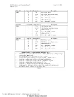
T-1 DEVICE TEST TABLE
Input Device
Display Panel
Description
Trouble / No
Feedback
Background Dirty
Pre-Alarm
on 1st
Alarm / Shorted/
Active
Ion Ionization
Detector
0 - 9
10 - 40
41 - 44
Background
+
26
Background
+
36
Opt. Photo
Detector
(non-comp.)
0 - 9
20 - 30
41 - 44
25 +
(sensitivity * 6)
+ 8
25 +
(sensitivity * 6)
+ 18
Opt.
Photo Detector
(Compensated)
0 - 9
10 - 40
41 - 44
Back
(sensitivity * 6)
+ 8
Back
(sensitivity * 6)
+ 18
Heat Thermal
Detector
0 - 7
10 - Fixed
Value
NA NA
Above Fixed
Value
CZI or CZII
CZI-95
0 - 16
17 - 54
NA NA
55 - 122
2nd Alarm
above 122
PID or MAN
PID - 95 or
MS - 95
0 - 9
10 - 54
N/A
N/A
55 - 127
REL
RCE - 95
0 - 14
15 - 45
NA NA
46 - 127
RSM
RSM-95
0 – 14
15 – 45
NA NA
46 - 127
SCE or Snd.
SCE - 95
0 - 14
15 - 45
NA NA
46 - 127
Output Test
The Output test function allows the user to individually test the functionality of
each device, operation and response.
Device LED will illuminate if selected for Output Test. The LED will turn off
when the device is deselected.
Function Programming
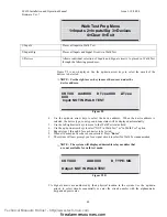
1=Walk Test 2=Bypass 3=Input Test
4=Output Test 5=Display 0=exit
>4
This displays in the same fashion as the Input Test
CKT:XX Add:XXX D_Type:XXX Counts: XX
Flags:xXX Bits:xXX
Technical Manuals Online! - http://www.tech-man.com
firealarmresources.com

