G
AMATRONIC
E
LECTRONIC
I
NDUSTRIES
L
TD
.
MegaV2 250 Installation Guide, Release 2.2
33
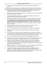
Figure 31: Verifying status of replacement module
19.
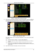
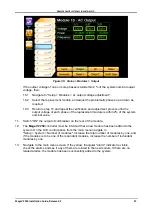
On the same screen ("Status > Modules"), press the Output button, select the replacement
module and verify that the output frequency matches the system nominal value, and that
the output voltage of each phase is within 2 % of the system nominal value.
Figure 32: Status > Modules > Output
If the output voltage of one or more phases is
not
within 2 % of the system nominal output
voltage, then:
19.1
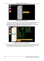
Navigate to "Setup > Modules > Ac output voltage adjustment".
19.2
Select the replacement module, and adjust the problematic phases up or down as
required.
19.3
Return to step 19 and repeat the verification and adjustment process until the
output voltage of each phase of the replacement module is within 2 % of the system
nominal value.
20
.
Switch "ON" the output circuit breaker on the rear of the module.

