G
AMATRONIC
E
LECTRONIC
I
NDUSTRIES
L
TD
.
MegaV2 250 Installation Guide, Release 2.2
16
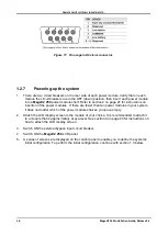
Figure 11: Pin usage in D9 alarm connector.
1.2.7
Powering-up the system
1.
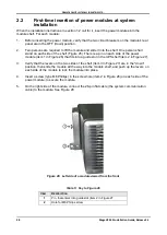
There are two circuit breakers on the rear side of each power module. Verify that on each
module the circuit breakers are in the OFF (down) position, then insert each power module
into a
MegaV2 250
power module shelf. Refer to section 2 on page 27 for instructions on
insertion of the power modules. If there are fewer than ten power modules in your system,
it does not matter which of the power module shelves you leave empty.
2.
Attach the LCD display screen to the module of your choice. It is recommended to attach it
to a module that is approximately at eye-level. See section 3 on page 40 for instructions on
how to attach the LCD display screen.
3.
Switch ON the external bypass input circuit breaker.
4.
Switch ON the
MegaV2 250
LCD panel.
5.
A series of screens are displayed on the control panel to enable you to define the system's
initial configuration. To perform the initial configuration, continue with section 1.3 below.


