background image

© All rights reserved - Galmet Sp. z o.o. Sp. K. 

Installation and Operating Manual / Warranty Card - SGW(S), SGW(S)B, SG(S)

3

1. Operation and service

1.1. Heater characteristics

Hot tap water heater is designed to heat water and store it in a heated state. It can be used to meet the needs of households in establishments catering, 
public welfare establishments, etc. The heater is designed to work only in horizontal or vertical position, depending on the type. It can be connected to the 
water supply at a pressure not exceeding 0,6 MPa - about 6 bar (in the case of tanks with capacity from 100 liters to 140 liters) and 1 MPa - about 10 bar (in 
the case of tanks with capacity from 200 liters to 1500 liters). The water can be heated by the spiral wound heat exchanger which (i.e. high surface area coil) 
connected to the central heating boiler. The basic model is a hot tap water heater with one coil (pt. 5.3; 5.5; 5.7). We offer water heaters with two spiral coils 
(bivalent): one coil for the CH system and the other for the solar heating system (pt. 5.10; 5.12; 5.14). Lower coil cooperates with a solar collector, and the 
top coil with the CH boiler or a heat pump. We offer hot tap water reservoirs (pt. 5.16; 5.18) and horizontal water heaters (pt. 5.18). Anticorrosion protection 
is provided by a ceramic enamel burned at 850°C. Moreover, large magnesium anode acts as an extra protection. Heaters are insulated with ecological 
polyurethane or polystyrene foam, which reduces heat loss to an absolute minimum.

1.2. Description

The main part of the heater is a tank in which the water is heated. The tank is made of a steel sheet, which is coated on the inside with ceramic enamel. 
Technological holes in the bottoms of the tank are closed with stoppers. The tank is equipped with two coil connections; the cold water outlet and inlet 
connections are located next to each other on one side of the tank. In addition, there is also provided an opening for connecting the circulation and the 
sensor cover - to which the sensor can be connected with the boiler thermostat (tube 3/8”). The standing heaters 100 to 140 l in the top of the bottom 
anode is located, which is placed on the stopper 5/4”. Tanks are from 200 to 1500 l, there are two magnesium anodes: one is arranged in the opening of 
the manhole M8 screw and the other is at the top of the bottom on the heels of 5/4” (200 - 500 l), 2” (700 - 1500 l). Heaters are equipped with additional 
connections (3/4 „ capacity. 100-140 l and 1” capacity. 200 -1500 l) where you can install the drain valve .

In the SGW(S)B 200 , SGW(S) SLIM 200-300 , SGW(S)B 200-300 SLIM and SGW(S) horizontal 140-300 water heaters it is recommended to install a tee on 
the cold water inlet as well as a the drain valve in order to properly drain the tank (pt. 2.3).

1.3.  Venting the coil in horizontal heaters

For easier (simpler) venting of the spiral coil it is necessary to:
-  put the tank in a vertical position (on the lid),
-  close the return from the coil (f.ex. by using a ball valve),
-  pour water or glycol solution into the coil (depending on the type of installation),
-  close the coil's supply connection (f.ex. by using a ball valve),
-  mount the tank on the frame (not included),
-  connect the tank to the installation.

1.4. Installation

Connection of the water heater should be done by the installer with the appropriate permissions. The installation must be confirmed in the warranty card. 
The heater must be installed in vertical or horizontal position depending on the type of the tank.

The heater should be connected directly to the water supply (with the possibility of disconnection, f.ex. in the case of maintenance) at a pressure not 
exceeding 0,6 MPa (tanks with the capacity between 100 and 140 l) and 1,0 MPa - about 10 bar (tanks with the capacity between 200 and 1500 l) while the 
minimum pressure shall be not less than 0,1 MPa (approx. 1 bar). If the water pressure in the mains supply exceeds 0,6 MPa tanks with the capacity between 
100 and 140 l) and 1,0 MPa - about 10 bar (tanks with the capacity between 200 and 1500 l) the pressure must be reduced by the use of a pressure regulator. 
Safety valve must be installed on the cold water supply pipe (f. ex. ZB4/ZB8 valves from FACH Cieszyn or ZB7/ZB9 valves from Orkla Spain) according to the 
direction of the arrow located on the tank. The safety valve can reduce pressure without the water overflowing to the supply installation (it opens the flow 
of the differential pressure in the heater and installation amounting to 0,07 0,03 MPa, which is why cold water supply pipe must withstand a temperature of 
90°C up to 5 meters from the safety valve (because of the possibility of the flow of hot water from the tank into the installation). An outflow opening in the 
safety valve must be constantly connected to the open atmosphere. Before using the installation it is necessary to check all of the connections for leakage, 

1. Operation and service

Summary of Contents for SG(S) 100

Page 1: ...W S Tower vertical SGW S BigTower vertical SGW S BTowerBiwal vertical SG S vertical SGW S horizontal Type Cover Colour Spiral coils 100 120 140 200 250 300 400 500 700 800 1000 1500 skay artificial leather white grey red blue Version standard slim one two bivalent two in the lower part of the tank without spiral coils Anode magnesium titanium option Insulation detachable non detachable Cat No Seri...

Page 2: ...cheme of the SGW S Tower Slim 200 300 11 5 6 Technical specification of the SGW S Tower Slim 800 1000 12 5 7 Scheme of the SGW S Tower Slim 800 1000 13 5 8 Technical specification of the SGW S BTower Biwal 200 1500 14 5 9 Scheme of the SGW S BTower Biwal 200 1500 15 5 10 Technical specification of the SGW S BTower Biwal Max 200 500 with two spiral coils at the bottom part of the tank 16 5 11 Schem...

Page 3: ...ttom on the heels of 5 4 200 500 l 2 700 1500 l Heaters are equipped with additional connections 3 4 capacity 100 140 l and 1 capacity 200 1500 l where you can install the drain valve In the SGW S B 200 SGW S SLIM 200 300 SGW S B 200 300 SLIM and SGW S horizontal 140 300 water heaters it is recommended to install a tee on the cold water inlet as well as a the drain valve in order to properly drain...

Page 4: ... The hose should be heat resistant up to 80 C with internal diameter of9mmandmax lengthof1 2m runtoadrainwithadowngrade min 3 inanenvironmentoftemperaturenotlowerthan0 C Thehosemustbe protected against bottlenecking squeezing plugging and its discharge end should be visible in order to verify operation of the valve 7 The water quality shall be in accordance with the Regulation of the Minister of H...

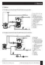
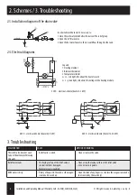
Page 5: ...r s housing Ks water outlet drain C circulation GE connection for the heating element W S spiral coil Tr thermometer Cz sensor cover 2 2 Exemplary connection scheme of the water heater in an closed system N expansion vessel Zb1 safety valve Zb2 CH installation safety valve Z1 shut off valve on cold water inlet Z2 shut off valve on hot water outlet Z3 Z4 shut off valve on water inlet from the heati...

Page 6: ...in the heating module 230V electrical scheme heater 2 3 kW grz grz grz L1 L2 L3 A1 A2 A3 B1 B2 B3 2 N PE 3 4 1 400V electrical scheme heater 4 5 9 kW 400V electrical scheme heater 12 24 kW 3 Troubleshooting MALFUNCTION CAUSE METHOD OF REMOVAL The relief valve does not open also at the attempt of blowing through Relief valve is seized Clean or replace the valve Relief valve leaks The faying surface...

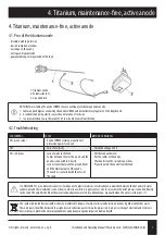
Page 7: ...n the electronic part and the anode is connected incorrectly Lack of contact between the ground tank and the electrical part of the anode The anode is contacted with the mass of the tank Fill the tank with water Put the cables at the anode Check and clean the rust all connections Properly isolate the anode from the tank It is NECESSARY to use a dielectric connectors made out of a plastic material ...

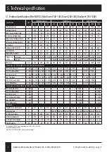
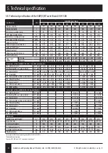
Page 8: ...onnections for the SGW S 100 400 700 1000 water heaters h1 Coldwaterinlet G mm 210 165 165 1 210 1 210 1 130 1 240 6 4 215 6 4 250 h2 CHwateroutflow G mm 310 250 250 1 290 1 285 1 280 1 320 1 375 1 450 h3 Sensorcover G mm R3 8 400 R3 8 375 R3 8 375 R3 8 435 R3 8 440 R3 8 435 R3 8 570 R3 8 575 R3 8 590 crk Circulation G mm 500 450 450 680 600 650 770 5 4 925 5 4 875 h4 CHhotwaterinflow G mm 710 750...

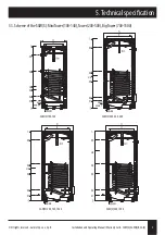
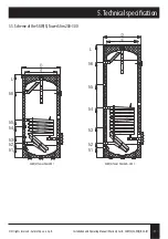
Page 9: ... Warranty Card SGW S SGW S B SG S 9 5 3 Scheme of the SGW S MiniTower 100 140 Tower 200 500 BigTower 700 1500 crk h3 h2 h1 h5 h4 SGW S 100 140 SGW S 200 250 400 crk h3 h2 h1 h5 h4 crk h3 h2 h1 h5 h4 SGW S 300 700 1000 SGW S 500 1500 crk h3 h2 h1 h5 h4 5 Technical specification ...

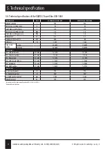
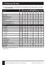
Page 10: ... 38x400 M8 screw 38x200 38x200 38x200 Connections for the SGW S Tower Slim 200 water heaters h1 Cold water inlet G mm 1 140 h2 CH water outflow G mm 1 225 h3 Sensor cover G mm 325 h4 Circulation G mm 485 h5 CH hot water inflow G mm 1 585 h6 DHW outflow G mm 1 1025 Connections for the SGW S Tower Slim 250 300 water heaters h1 Cold water inlet G mm 1 140 1 140 h2 CH water outflow G mm 1 225 1 225 h3...

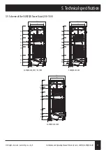
Page 11: ... o Sp K Installation and Operating Manual Warranty Card SGW S SGW S B SG S 11 5 5 Scheme of the SGW S Tower Slim 200 300 h1 L h2 h3 h4 h5 h6 h1 L h2 h3 h4 h5 h6 SGW S Tower Slim 200 I SGW S Tower Slim 250 300 l 5 Technical specification ...

Page 12: ...MPa 1 6 1 6 Coil surface m2 2 4 3 7 Coil power 70 10 45 C kW 44 5 60 Efficiency l h 1099 1468 Magnesium anode 2 plug 38x600 38x600 5 4 plug 38x400 38x400 Connections h1 Cold water inlet G mm 6 4 210 6 4 210 h2 CH water outflow G mm 1 380 1 380 h3 Sensor cover G mm 610 610 h4 CH hot water inflow G mm 1 1030 1 1265 h5 Circulation G mm 5 4 1352 5 4 1640 h6 DHW outflow G mm 6 4 1610 6 4 1910 Dimension...

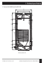
Page 13: ...l rights reserved Galmet Sp z o o Sp K Installation and Operating Manual Warranty Card SGW S SGW S B SG S 13 5 7 Scheme of the SGW S Tower Slim 800 1000 SGW S Tower Slim 800 1000 5 Technical specification ...

Page 14: ... 375 1 450 h3 Sensor cover I G mm R 3 8 355 R 3 8 400 R 3 8 435 R 3 8 570 R 3 8 575 R 3 8 590 crk Circulation G mm 450 595 650 770 5 4 925 5 4 880 h4 Hot water inflow from solar collector G mm 1 550 1 695 1 750 1 870 1 1045 1 1000 h5 CH water outflow G mm 1 635 1 795 1 860 1 980 1 1175 1 1100 h6 Sensor cover II G mm 3 8 765 3 8 900 3 8 1030 3 8 1150 3 8 1365 3 8 1250 h7 CH hot water inflow G mm 1 ...

Page 15: ...rating Manual Warranty Card SGW S SGW S B SG S 15 5 9 Scheme of the SGW S BTower Biwal 200 1500 crk h3 h2 h1 h5 h6 h7 h8 h4 crk h3 h2 h1 h5 h6 h7 h8 h4 SGW S B 200 300 700 1000 SGW S B 250 400 SGW S B 500 1500 crk h3 h2 h1 h5 h6 h7 h8 h4 5 Technical specification ...

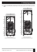
Page 16: ... 24 24 43 48 Additional source coil s power 70 10 45 C kW 24 24 24 24 Dimensions h1 Cold water inlet G mm 1 130 1 130 1 160 1 160 h2 Coil return I G mm 1 210 1 180 1 240 1 240 h3 Coil return II G mm 1 280 1 250 1 325 1 340 h4 Sensor cover I G mm 3 8 380 3 8 350 3 8 475 3 8 510 h5 Sensor cover II G mm 3 8 480 3 8 475 3 8 625 3 8 640 h6 Coil supply II G mm 1 580 Circulation 1 590 1 905 1 990 h7 Coil...

Page 17: ...S BTower Biwal Max 200 500 with two spiral coils at the bottom part of the tank d D h7 h5 h3 h2 0 h4 h6 L h8 h9 d D h7 h5 h3 h2 h1 0 h4 h6 L h8 h9 SGW S BTower Biwal Max 200 with two spiral coils at the bottom part of the tank SGW S BTower Biwal Max 300 500 with two spiral coils at the bottom part of the tank 5 Technical specification ...

Page 18: ...GW S BTower Biwal Slim 200 water heaters h1 Cold water inlet G mm 1 140 h2 Water outflow to solar collector G mm 1 225 h3 Sensor cover I G mm 325 h4 Circulation G mm 1 485 h5 Hot water inflow from solar collector G mm 1 585 h6 CH water outflow G mm 695 h7 Sensor cover II G mm 820 h8 CH hot water inflow G mm 1 945 h9 DHW outflow G mm 1 1025 Connections for the SGW S BTower Biwal Slim 250 300 water ...

Page 19: ... and Operating Manual Warranty Card SGW S SGW S B SG S 19 5 13 Scheme of the SGW S BTower Biwal Slim 200 300 h1 L h2 h3 h4 h5 h6 h7 h8 h9 h1 L h2 h3 h4 h5 h6 h7 h8 h9 SGW S BTower Biwal Slim 200 I SGW S BTower Biwal Slim 250 300 l 5 Technical specification ...

Page 20: ...CH coil s surface m2 1 2 1 8 CH coil s power 70 10 45 C kW 24 5 39 CH coil s efficiency l h 600 958 Magnesium anode 2 plug 38x600 38x600 5 4 plug 38x400 38x400 Connections h1 Cold water inlet G mm 6 4 210 6 4 210 h2 Water outflow to solar collector G mm 1 380 1 380 h3 Sensor cover I G mm 610 610 h4 Hot water inflow from solar collector G mm 1 1030 1 1265 h5 CH water outflow G mm 1 1145 1 1380 h6 S...

Page 21: ...s reserved Galmet Sp z o o Sp K Installation and Operating Manual Warranty Card SGW S SGW S B SG S 21 5 15 Scheme of the SGW S BTower Biwal Slim 800 1000 SGW S BTower Biwal Slim 800 1000 5 Technical specification ...

Page 22: ...70 h6 DHW outflow Gw 3 4 mm 790 920 1070 Connections for the SG S 200 400 tanks h1 Water drain Gw 1 mm 130 160 h2 Cold water inlet Gw 1 mm 210 240 h3 Sensor cover I Gw 1 2 mm 440 570 h4 Sensor cover II Gw 1 2 mm 1100 h5 Circulation Gw 3 4 mm 680 1200 h6 DHW outflow Gw 3 4 mm 865 1480 Connections for the SG S 300 500 tanks h1 Water drain Gw 3 4 mm 130 180 h2 Cold water inlet Gw 3 4 mm 205 260 h3 Se...

Page 23: ... reserved Galmet Sp z o o Sp K Installation and Operating Manual Warranty Card SGW S SGW S B SG S 23 5 17 Scheme of the SG S 100 500 SG S 100 140 SG S 200 400 SG S 300 500 h1 h2 h3 h4 h5 5 Technical specification ...

Page 24: ...lug 38x200 38x400 38x400 Connections h1 Cold water inlet Gw 6 4 mm 250 270 270 h2 Additional source inlet Gw 6 4 mm 360 380 380 h3 Sensor cover I Gw 1 2 mm 650 600 600 h4 Additional source inlet Gw 6 4 mm 1270 1105 1750 h5 Sensor cover II Gw 1 2 mm 1330 1200 1630 h6 Circulation Gw 5 4 mm 1470 1290 1950 h7 DHW outflow Gw 6 4 mm 1750 1570 2250 Dimensions d Internal diameter Ø 700 900 900 D External ...

Page 25: ... All rights reserved Galmet Sp z o o Sp K Installation and Operating Manual Warranty Card SGW S SGW S B SG S 25 5 19 Scheme of the SG S 700 1500 SG S 700 1500 5 Technical specification ...

Page 26: ...45 C kW 23 24 24 Efficiency l h 560 570 570 Coil power 80 10 45 C kW 30 4 32 32 Efficiency l h 740 760 760 Demand for heating water from CH boiler m3 h 2 6 2 9 2 9 Magnesium anode 5 4 plug 25x390 38x200 38x200 M8screw 38x400 38x400 Connections h1 Cold water inlet 1 mm 175 235 235 h2 CH water outflow 1 mm 275 275 h3 Circulation 3 4 mm 375 315 485 h4 Sensor cover 1 2 mm 535 700 h5 CH hot water inflo...

Page 27: ...omy z wężownica spi Typ Jedn SGW S poziomy 140 S pozi Pojemność l 140 Max ciśnienie pracy zbiornika MPa Max ciśnienie wężownicy MPa Pow wymiennika do c o m2 0 95 Moc wymiennika do c o 70 10 450 C kW 23 Wydajność l h 560 Moc wymiennika do c o 80 10 450 C kW 30 4 Rysunek nr 9 Podgrzewacz 140 l Rysunek nr 10 Podgrzewacz 200 300 l 5 6 mounting bracket feet connection for circulation connectionfor circ...

Page 28: ...W The wall thickness of the jackets and the bottoms as well as the material the exchangers were made of are listed below Type Diameter Ø Bottoms Material Jackets Material Material thickness Material thickness SG S 100 400 2 0 S235JR 2 0 S235JR SG S 120 400 2 0 2 5 SG S 140 400 2 0 2 5 SG S 200 550 3 0 2 5 SG S 300 550 3 0 2 5 SG S 400 600 3 5 3 0 SG S 500 630 3 5 3 0 SG S 700 708 3 5 3 8 SG S 1000...

Page 29: ...l as the material the exchangers were made of are listed below Type Diameter Ø Bottoms Material Jackets Material Material thickness Material thickness SGW S MiniTower 100 400 2 0 S235JR 2 2 S235JR SGW S MiniTower 120 400 2 0 2 2 SGW S MiniTower 140 400 2 0 2 2 SGW S horizontal 140 400 2 5 2 5 SGW S Tower Slim 200 500 3 0 2 5 SGW S Tower 200 550 3 0 2 5 SGW S horizontal 200 550 3 0 2 5 SGW S Tower ...

Page 30: ...ets and the bottoms as well as the material the exchangers were made of are listed below Type Diameter Ø Bottoms Material Jackets Material Material thickness Material thickness SGW S BTower Biwal Slim 200 500 3 0 S235JR 2 5 S235JR SGW S BTower Biwal 200 550 3 0 2 5 SGW S BTower Biwal Slim 250 500 3 0 2 5 SGW S BTower Biwal 250 550 3 0 2 5 SGW S BTower Biwal Slim 300 500 3 0 2 5 SGW S BTower Biwal ...

Page 31: ... Tower Slim ErP class C 1 EN Supplier s name or trade mark Galmet 2 EN Supplier s model identifier SGW S SLIM 200 SGW S SLIM 250 SGW S SLIM 300 3 EN Energy efficiency class C C C 4 EN Standing loss W 75 83 92 5 EN Storage volume L 205 247 292 7 3 SGW S Tower Slim ErP class A 1 EN Supplier s name or trade mark Galmet 2 EN Supplier s model identifier SGW S SLIM 200 SGW S SLIM 250 SGW S SLIM 300 3 EN...

Page 32: ...A A A 4 EN Standing loss W 42 46 48 5 EN Storage volume L 199 240 286 7 8 SGW S BTower Biwal Max 1 EN Supplier s name or trade mark Galmet 2 EN Supplier s model identifier SGW S Bd 200 SGW S Bd 300 SGW S Bd 400 SGW S Bd 500 3 EN Energy efficiency class B B C B 4 EN Standing loss W 60 67 95 82 5 EN Storage volume L 197 300 396 497 7 9 SG S 1 EN Supplier s name or trade mark Galmet 2 EN Supplier s m...

Page 33: ...bleddirectlyinfrontoftheheateronthepipesupplyingitwithcoldwater Onlyvalvesacceptablebyadequateorgansshould beused adjustedtostoragewaterheaters Safetyvalveshouldbeusedaccordingtotheoperatingmanualforthevalve 9 Itisstrictlyforbiddentoassembleadditionalequipment e g shut offvalve checkvalveetc betweenthesafetyvalveandtheheater Itisonlyrecommended toassembleathree way adapterinordertoemptytheheater 1...

Page 34: ...emethodforrepairshallbespecifiedbythemanufacturer 21 Multiple repairs will not include the following heater adjustment replacement of magnesium anode replacement of gaskets nor any element wearing duringnormaloperationoftheequipment 22 Themanufacturershallexcludetheirliabilitybyvirtueofanysuretyforphysicaldamagesoftheequipment Thebuyershallbeentitledtoaguaranteebased onprinciples withinperiodandmo...

Page 35: ...of repair Service s seal Service s seal Service s seal Service s seal Owner s name and address Owner s name and address Owner s name and address Owner s name and address Owner s signature Owner s signature Owner s signature Owner s signature No Date of receipt Description of the repair Date of workmanship Serviceman s signature ...

Page 36: ... Installation confirmation Type Factory no Date of sale Seller s stamp and signature Warranty coupon 1 Warranty coupon 2 Warranty coupon 3 Warranty coupon 4 Type Type Type Type Factory no Factory no Factory no Factory no Date of sale Date of sale Date of sale Date of sale Seller s stamp and signature Seller s stamp and signature Seller s stamp and signature Seller s stamp and signature ...

Reviews: