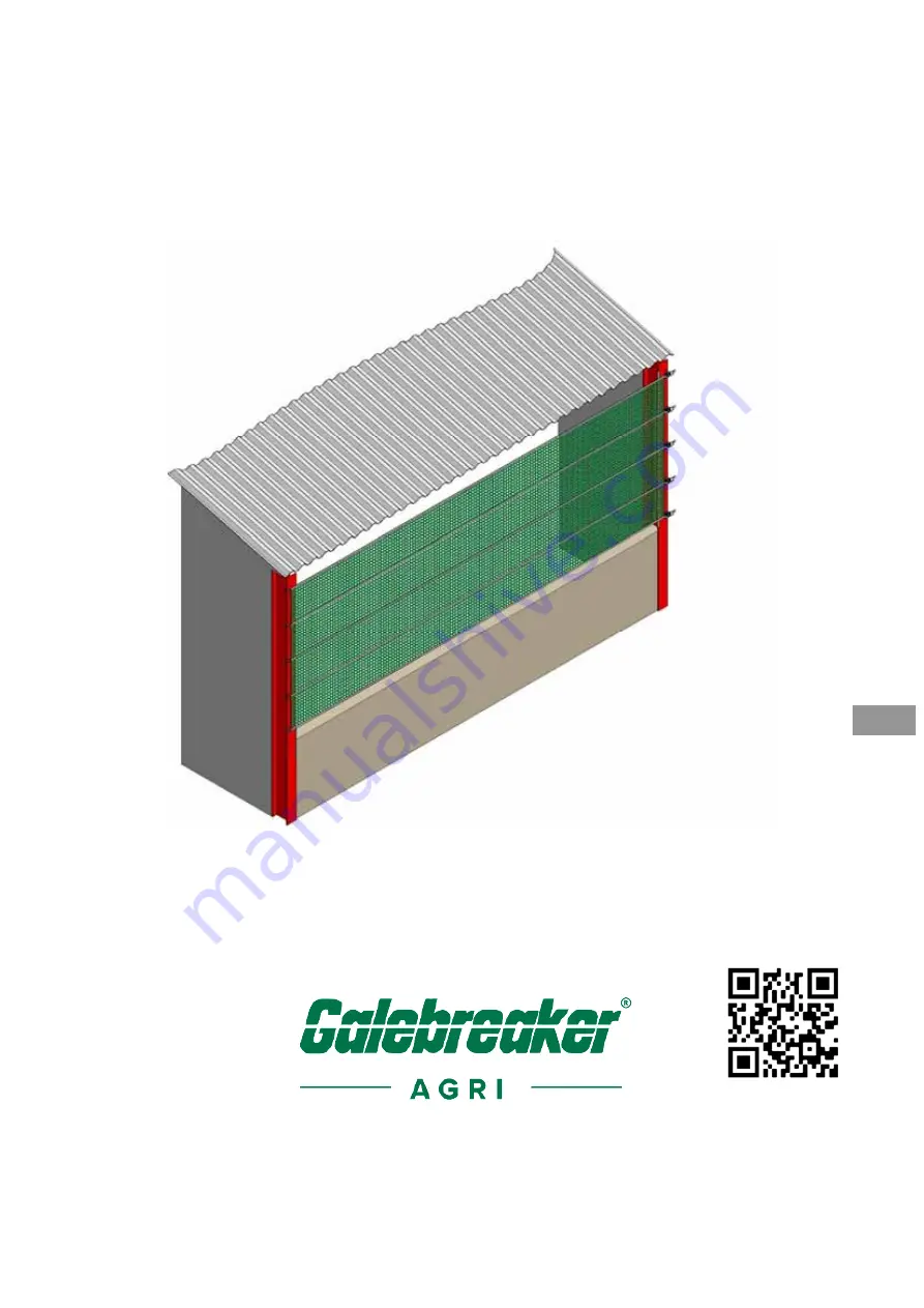
Bayscreen
®
Installation and Operating
Instructions
ENG
To watch video scan QR code with phone camera
Page 1: ...Bayscreen Installation and Operating Instructions ENG To watch video scan QR code with phone camera...
Page 2: ...Bayscreen Introduction 2 Figure 1 System Overview and Individual Components...
Page 3: ...L 10m C2 3 4 5 7 25mm Cranked Hook L 10m D1 3 4 5 7 50mm Ratchet Hook L 10m D2 3 4 5 7 25mm Ratchet Hook L 10m E1 3 4 5 7 50mm Ratchet L 10m E2 3 4 5 7 25mm Ratchet 6 5m L 10m E3 3 4 5 7 25mm Ratchet...
Page 4: ...ller Items Required By The Installer Standard tool kit including Sharp pair of scissors or knife Electric drill L 15m Key Instructions ATTENTION Observe the given instructions otherwise the product or...
Page 5: ...s where the building columns are of H Beam construction but opposite orientation or manufactured from timber or concrete Figure 3 Fixing Variations Steel angle on concrete upright Steel angle on H Bea...
Page 6: ...B1 over the inner edges of the pillars Figure 4 If you are unable to use these protectors due to the building design then it is important sharp objects and rough surfaces are covered with PVC strip o...
Page 7: ...ns 5 If necessary trim the screen to the required length For best results use sharp scissors knife with a straight edge to remove the fabric either side of the webbing strap ensuring all corners have...
Page 8: ...ets E1 using the M12x130 bolts and nuts F1 with two ratchet spacers F2 each side of the ratchet Figure 6a Figure 6a 50mm Hook and Ratchet Assembly 6 2 If L 10m clip the 25mm ratchet hook D2 to the 25m...
Page 9: ...other to provide good tension to the vertical edges of the Bayscreen Figure 7 Figure 7 Tensioning the Screen 8 Tighten all ratchets as firmly as possible applying the tension equally to avoid wrinkles...
Page 10: ...g pull ratchet release catch on handle and open 180 degrees until ratchet body is flat and pull on webbing strap Mounting Screens in Series 9 When screens are installed in series they share a common p...
Page 11: ...minimise screen sag we recommend it is positioned to within 1m of the centre Assemble the ratchet bracket assembly E1 with the M12 x 85mm bolt C provided Figure 9 depicts the standard fitting of the b...
Page 12: ...as shown in Figure 9 The clamp plates bolt either side of the webbing pierce holes through the fabric for the bolts and not through the webbing Feed webbing G1 through ratchet and ensuring at least 15...
Page 13: ...your Galebreaker dealer importer or head office How to dismantle your Bayscreen i To remove the webbing from the ratchet pull the release catch on the handle and open 180 degrees until the ratchet bod...
Page 14: ...Bayscreen Notes 14 ENG...
Page 15: ...Bayscreen Notes 15 ENG...
Page 16: ...Copyright Galebreaker Agri Ltd 2021 All Rights reserved Model No B MK3 05 02 Instruction Ver 2021 03 ENG Manufacturer Galebreaker Agri Ltd Tel 44 0 1531 637 900 Galebreaker House Fax 44 0 1531 637 901...