background image


Gala Cut 700 


ES  MANUAL TÉCNICO DE INSTRUCCIONES.  

EN  TECHNICAL INSTRUCTIONS MANUAL.  

FR  MANUEL TECHNIQUE D'INSTRUCTIONS.  


Ref. 463.00.00 

GALA CUT 700 

(400-440V - 50/60Hz)


ES


ESTE EQUIPO DEBE SER UTILIZADO POR PROFESIONALES. 

EN BENEFICIO DE SU TRABAJO LEA ATENTAMENTE ESTE MANUAL.


EN 


THIS EQUIPMENT SHOULD BE USED ONLY BY PROFESSIONALS. 

FOR THE BENEFIT OF YOUR WORK, PLEASE READ THIS MANUAL CAREFULLY. 

FR 


CE POSTE DE DÉCOUPE PLASMA DOIT ÊTRE UTILISÉ PAR DES PROFESSIONNELS. 

POUR OBTENIR UN RÉSULTAT OPTIMUM, LIRE ATTENTIVEMENT CE MANUEL. 


Ref. 46317047/ Ed.3 


Jaime Ferrán, 19 

● 50014 ZARAGOZA (SPAIN) 

Tel.: +34 976473410 

● Fax: +34 976472450 

E-mail: [email protected] 

● 

Web: www.galagar.com 

Summary of Contents for 463.00.00

Page 1: ... DE SU TRABAJO LEA ATENTAMENTE ESTE MANUAL EN THIS EQUIPMENT SHOULD BE USED ONLY BY PROFESSIONALS FOR THE BENEFIT OF YOUR WORK PLEASE READ THIS MANUAL CAREFULLY FR CE POSTE DE DÉCOUPE PLASMA DOIT ÊTRE UTILISÉ PAR DES PROFESSIONNELS POUR OBTENIR UN RÉSULTAT OPTIMUM LIRE ATTENTIVEMENT CE MANUEL Ref 46317047 Ed 3 Jaime Ferrán 19 50014 ZARAGOZA SPAIN Tel 34 976473410 Fax 34 976472450 E mail info galag...

Page 2: ...SPORT AND INSTALLATION 15 3 START UP OPERATION AND ADJUSTMENTS 16 4 MAINTENANCE OPERATIONS RECOMMENDATIONS 20 5 ANOMALIES PROBABLE CAUSES POSSIBLE SOLUTIONS 22 6 SAFETY MEASURES 23 APPENDICES DECLARATION OF CONFORMITY EC MARKING ELECTRICAL DRAWINGS DETAIL DRAWINGS AND REFERENCE LISTS FR TABLE DES MATIÈRES Page 1 DESCRIPTION GÉNÉRALE CARACTÉRISTIQUES TECHNIQUES 25 2 TRANSPORT ET INSTALLATION 26 3 M...

Page 3: ...mm 30 mm Margen de regulación de la corriente de corte I2 20 70 A Intensidad máxima de corte 70 A 60 55 A 100 Antorcha incorporada P 80 Compresor recomendado 4 CV 480 l min Sistema semiautomático de filtro y descarga SI Modo de trabajo de reignición Corte de enrejados SI Proceso de gubiado SI Protección sobrecalentamiento Falta presión SI Grado de protección mecánica IP 21 S Dimensiones ANCHOXLARG...

Page 4: ...ica Elementos eléctricos de la instalación Sistema de protección Gala Cut 700 Clavija de conexión 16A 3P T Interruptor magnetotér mico Curva D 3P 15 A Interruptor diferencial Mínimo 3P 25A 300 mA NO OLVIDE CONECTAR LA TOMA DE TIERRA EN LA CLAVIJA Manguera de alimentación RVK 1KV GALA CUT 700 Longitud 400 440 V 15 m 2 5 mm2 15 50 m 4 mm2 LAS INSTALACIONES ELECTRICAS SOLO DEBEN SER MANIPULADAS POR P...

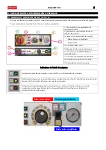
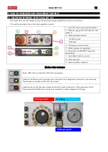
Page 5: ...ión de presión de trabajo 6 Conector control ON OFF para automatización 7 Conector centralizado de antorcha 8 Interruptor de puesta en marcha 9 Indicados de estado máquina Indicadores de Estado de máquina Led verde indicación de puesta en marcha ON con alimentación de entrada Indicación de Ausencia de porta tobera en el cabezal de antorcha Se impide funcionamiento de equipo por la situación peligr...

Page 6: ...elector marca 3 Posición 1 Modalidad de corte general en plano enrejillados y corte a contacto Mod A y B Posición 2 Descarnado o Gouging 7 Conectar el equipo y regular la corriente de soldadura deseada mediante el potenciómetro 1 8 Puede comenzar la operación de 9 corte 3 3 MODALIDADES DE TRABAJO SELECCIÓN Y COLOCACION DE ACCESORIOS Pueden plantearse 3 modalidades de trabajo que requerirán KIT de ...

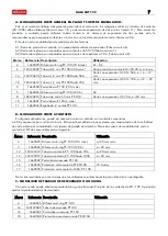
Page 7: ...5124815 Tobera de corte 1 5 mm PT 100 Corte con separador I2 70 A e 20 mm 10 1660501 Porta tobera P 100 A máx 11 1660444 Espaciador 2 puntas PT 100 B MODALIDAD DE CORTE A CONTACTO En algunas aplicaciones puede ser necesario cortar a contacto con corrientes superiores a 40 A y espesores por encima de 6 mm Esto puede ser debido a que se desea una maximización de la velocidad de corte o bien por como...

Page 8: ...iere que el equipo esté conectado a la red neumática debe existir presión de aire Comience el corte desde el borde la pieza Para cortar puede apoyar la antorcha en la pieza pero no ejerza presión La velocidad de corte depende del espesor de la pieza Si la pieza tiene un espesor inferior a 5 mm puede comenzar el corte desde el interior de la pieza como se indica en la figura Durante el corte manten...

Page 9: ... Verifique el estado y la idoneidad de los accesorios para el trabajo a realizar SEMANAL La antorcha dispone de un interruptor de seguridad Verifique que con el porta tobera quitado jamás se enciende el indicador 6 tras pulsar la antorcha 3 MESES Verifique que los aislamientos de mangueras de alimentación y antorchas no han sufrido desperfectos El proceso de corte desprende materiales a altas temp...

Page 10: ...dera Material de medida y calibración Para reducir las molestias por CEM tenga en cuenta la hora del día en que la soldadura u otras actividades se llevarán a cabo Aleje las posibles víctimas de interferencias de la instalación de soldadura El aparato siguiendo la clasificación EMC de equipos según la CISPR 11 atiende al grupo 1 clase A CONECTE SIEMPRE LA MÁQUINA A LA ALIMENTACIÓN CON UNA TOMA DE ...

Page 11: ... de alimentación NO HAY ARCO PILOTO Y LED DE PRESIÓN ENCEDIDO Falta de presión Alimentar con aire y regular Mínimo a 4 0 Bar NO HAY ARCO PILOTO LED TENSION DE SEGURIDAD Porta tobera mal colocado Colocar correctamente el porta toberas HAY ARCO PILOTO PERO NO CORTA Olvidó la Masa Colocar la masa a la pieza a cortar Velocidad de corte elevada Reduzca la velocidad HAY ARCO PILOTO PERO SE APAGA Tensión...

Page 12: ...ateriales que incorporen algún tipo de tratamiento superficial cincado galvanizado etc Evítese en todo momento la inhalación de los humos desprendidos en el proceso Protéjase del humo y polvo metálico que pueda originarse Utilice máscaras anti humo homologadas El trabajo con estos equipos debe realizarse en locales o puestos de trabajo donde exista una adecuada renovación de aire La realización de...

Page 13: ...GALA CUT 700 13 ...

Page 14: ...tting thickness separation 25 mm 30 mm Cutting current regulation margin I2 20 70 A Maximum cutting intensity 70 A 60 55 A 100 Built in torch P 80 Recommended compressor 4 CV 480 l min Semi automatic filter and discharging system YES Reignition work mode Grating cutting YES Gouging process YES Protection against overheating pressure drop YES Degree of IP mechanical protection IP21S Dimensions W x ...

Page 15: ...llation Electrical elements of the installation Protection system Gala Cut 700 Connection plug 16A 3P T Magnetother mal switch Curve D 3P 15 A Differential circuit breaker Minimum 3P 25A 300 mA DO NOT FORGET TO FIT THE EARTH CONNECTION INTO THE PLUG Power supply hose RVK 1KV GALA CUT 700 Length 400 440 V 15 m 2 5 mm2 15 50 m 4 mm2 ELECTRICAL INSTALLATIONS SHOULD ONLY BE HANDLED BY SPECIALISED PERS...

Page 16: ...utting ground connector 5 Working pressure regulation 6 Connector for ON OFF control of Automation 7 Centralised torch connector 8 Start up switch 9 Machine Status Indicator Machine Status Indicators Green LED start up indication ON with input power Indication of Absence of retaining cap in the torch head Equipment operation is prevented by the dangerous situation which may be caused Indication of...

Page 17: ...5 Determine Work Mode by item 3 selector Position 1 General cutting mode on flat grids and contact cutting Mod A and B Position 2 Gouging 16 Connect the equipment and adjust the desired working current using the potentiometer 1 17 You can now start the cutting operation 3 3 WORKING MODES SELECTION AND INSTALLATION OF ACCESSORIES You can consider 3 work modes that will require a specific spare part...

Page 18: ...815 Cutting tip 1 5 mm PT 100 Cutting with spacer I2 70 A e 20 mm 10 1660501 Retaining cap P 100 A max 11 1660444 Two points spacer PT 100 B CONTACT CUTTING MODE In some applications it may be necessary to carry out contact cutting with currents greater 40 A and thicknesses above 6 mm This may be the case because the maximisation of cutting speed is desired or for convenience in the torch guidance...

Page 19: ... requires the equipment to be connected to the pneumatic network there must be air pressure Start the cut from the edge of the piece To cut you can rest the torch on the workpiece but do not apply pressure The cutting speed depends on the thickness of the piece If the piece is less than 5 mm thick you can start cutting from the inside of the piece as indicated in the figure During cutting keep the...

Page 20: ...Check the condition and suitability of the accessories for the work to be done WEEKLY The torch has a safety switch Verify that with the retaining cap removed indicator 6 never lights up after pressing the torch QUARTERLY Check that the torch and feed hose insulations have not been damaged The cutting process releases materials at high temperatures that can damage them Blow out the interior of the...

Page 21: ...h pacemakers or hearing aids Measurement and calibration equipment In order to reduce EMC problems keep in mind the time of day when cutting or other activities will be carried out Move possible interference victims away from the cutting station The device following the EMC classification of equipment according to CISPR 11 meets group 1 class A ALWAYS CONNECT THE MACHINE TO POWER GRID USING AN EFF...

Page 22: ...LED ON Lack of pressure Provide air and regulate Minimum at 4 0 Bar NO PILOT ARC AND SAFE VOLTAGE LED ON Retaining cap incorrectly positioned Place it in its correct position THERE IS A PILOT ARC BUT IT DOES NOT GO OUT You forgot to connect the ground clamp Connect the ground clamp to the piece to be cut The cutting speed is very high Reduce the speed THERE IS PILOT ARC BUT IT GOES OUT Low mains v...

Page 23: ...can also occur with those materials which have some kind of surface coating zinc plated galvanised etc Avoid inhaling the fumes given off in the process at all times Protect yourself from the fumes and metal dust which can be given off Use quality approved anti fume goggles Work with this equipment must be carried out in places or workstations where there is suitable air renewal If cutting process...

Page 24: ...GALA CUT 700 24 NOTES ...

Page 25: ...tion 25 mm 30 mm Plage de réglage du courant de coupe I2 20 70 A Intensité maximum de coupe 70 A 60 55A 100 Torche intégrée P 80 Compresseur recommandé 4 CV 480 l min Système semi automatique de filtre et décharge OUI Mode de travail de réallumage Coupe de grilles OUI Procédé de Gougeage OUI Protection contre surchauffe chute de pression OUI Degré de protection mécanique IP21S Dimensions Largeur x...

Page 26: ...ectrique Éléments électriques de l installation Système de protection Gala Cut 700 Connecteur de branchement 16A 3P T Interrupteur magnétother mique Courbe D 3P 15 A Interrupteur différentiel Minimum 3P 25A 300 mA NE PAS OUBLIER DE BRANCHER LA PRISE DE TERRE À LA FICHE Câble d alimentation RVK 1KV GALA CUT 700 Longueur 400 440V 15 m 2 5 mm2 15 50m 4 mm2 LES INSTALLATIONS ÉLECTRIQUES NE DOIVENT ÊTR...

Page 27: ... de travail 6 Connecteur pour contrôle ON OFF d automatisation 7 Connecteur de torche centralisé 8 Interrupteur général de mise en marche 9 Indicateurs d état de la machine Indicateurs d état de la machine LED vert indiquant la mise en marche ON avec alimentation d entrée Indication d absence de porte buses sur la tête de la torche Le fonctionnement de la machine est arrêté compte tenu de la situa...

Page 28: ...e sélecteur item 3 Position 1 Modalité de coupe générale sur plain grilles et coupe par contact Mod A et B Position 2 Gougeage ou Gouging 24 Brancher la machine et régler le courant de travail souhaité au moyen du potentiomètre 1 25 L opération de coupe peut commencer 3 3 MODALITÉS DE TRAVAIL SÉLECTION ET INSTALLATION DES ACCESSOIRES 3 modalités de travail requérant des kits de pièces de rechange ...

Page 29: ... A3 8 165124815 Tuyère de coupe 1 5 mm PT 100 Coupe avec patin I2 70 A e 20 mm 10 1660501 Buse P 100 A max 11 1660444 Patin 2 pointes PT 100 B MODALITÉ DE COUPE PAR CONTACT Pour certaines applications avec des courants supérieurs à 40 A et des épaisseurs supérieures à 6 mm une coupe par contact peut être nécessaire Cela peut être dû au souhait d une maximisation de la vitesse de coupe ou par commo...

Page 30: ...la machine soit connectée au réseau pneumatique il doit y avoir une pression d air Commencer la coupe à partir du bord de la pièce Pour couper vous pouvez faire reposer la torche sur la pièce mais sans exercer de pression La vitesse de coupe dépend de l épaisseur de la pièce Si la pièce a une épaisseur inférieure à 5 mm la coupe peut être commencée de l intérieur de la pièce tel que l indique la f...

Page 31: ... Vérifier l état et l adéquation des accessoires pour l opération à réaliser TOUTES LES SEMAINES La torche dispose d un interrupteur de sécurité Une fois le buse retiré l indicateur 6 ne doit jamais s allumer après avoir appuyé sur la torche TOUS LES 3 MOIS Vérifier que les isolations des tuyaux d alimentation et des torches ne soient pas abîmées Le procédé de coupe entraînent l apparition de mati...

Page 32: ... Matériel de mesure et de calibrage Pour réduire les gênes dues aux CEM tenir compte de l heure où le coupage et les autres activités seront réalisés Éloigner les éventuelles victimes d interférences de l installation du poste de découpe plasma L appareil suivant la classification EMC d équipements selon la CISPR 11 rentre dans le groupe 1 classe A TOUJOURS BRANCHER LA MACHINE À UNE PRISE DE MASSE...

Page 33: ...r la tension d alimentation IL N Y A PAS D ARC PILOTE ET LE LED DE PRESSION EST ALLUMÉ Manque de pression Alimenter d air et régler 4 0 bars minimum IL N Y A PAS D ARC PILOTE LA LED DE TENSION DE COUPE NE S ALLUME PAS Buse mal installée Installer correctement le buse IL Y A UN ARC MAIS PAS DE COUPE Masse oubliée Brancher la masse à la pièce à couper Vitesse de coupe élevée Réduire la vitesse IL Y ...

Page 34: ...ut également avoir lieu avec tout matériel ayant reçu un traitement de surface zingage galvanisation etc Éviter à tout moment l inhalation des fumées de coupage Utiliser une protection contre la fumée et la poussière Utiliser des masques antifumée homologués Le travail avec ces postes de découpe plasma doit être réalisé dans des endroits ou postes de travail bien aéré La réalisation du procédé de ...

Page 35: ...GALA CUT 700 35 NOTES ...

Page 36: ...ny additional charge unless the damage caused to the product is the result of accidents improper use negligence inappropriate accessories unauthorized servicing or modifications to the product not carried out by GALA GAR The decision to repair or replace parts or supply a new appliance shall be at the discretion of GALA GAR All replaced parts and products will be the property of GALA GAR In order ...

Page 37: ...Esquema eléctrico Gala Cut 700 U1 3Ph 400 440 V 50 60 Hz Ref 46300000 13 08 2014 ...

Page 38: ...REPUESTOS GALA CUT 700 REF 46300000 28 6 17 HR 46300000V2 1 2 3Ph 400 440 V 50 60Hz ...

Page 39: ...REPUESTOS GALA CUT 700 REF 46300000 11 6 20 HR 46300000V3 2 2 3Ph 400 440 V 50 60Hz A PLASMA TORCH REF 1609740 B NEUMATIC FILTER REF 50916012 C INLET FILTER COUPLING REF 45001019 A B C ...

Page 40: ...5124610 Tobera 1 0 mm PT 100 Hasta 50 A 7b 165124612 Tobera 1 2 mm PT 100 Hasta 70 A 8 165124815 Tobera de corte 1 5 mm PT 100 9 1660500 Portatobera P 100 70 a MAX 10 1660501 Portatobera P 100 120A MAX 11 1660444 Espaciador 2 puntas PT 100 12 165127612 Tobera a contacto PT 100 hasta 70A 13 165127815 Tobera a contacto PT 100 hasta 100A 14 165127822 Tobera descarnado PT 100 15 1660502 Portatobera ro...

Page 41: ...rl ring PT 100 120 A A3 8 165124815 Tobera de corte 1 5 mm PT 100 Corte con separador I2 70 A e 20 mm 10 1660501 Portatobera P 100 120A MAX 11 1660444 Espaciador 2 puntas PT 100 B MODALIDAD DE CORTE A CONTACTO En algunas aplicaciones puede ser necesario cortar a contacto con corrientes superiores a 40 A y espesores por encima de 6 mm Esto puede ser debido a que se desea una maximización de la velo...

Page 42: ...Gala Gar S L C Jaime Ferrán 19 50014 Zaragoza SPAIN Tel 34 976 47 34 10 Fax 34 976472450 E mail info galagar com Web www galagar com ...

Reviews: