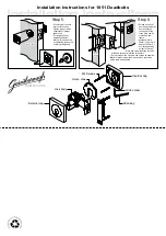
Installation Instructions for 1851Deadbolts
Fit here on door edge
Fit here on door edge
BACKSET
60mm (2 3/8"
)
Mark centre-line
of latch hole
Mark centre-line
of latch hole
FOLD HERE
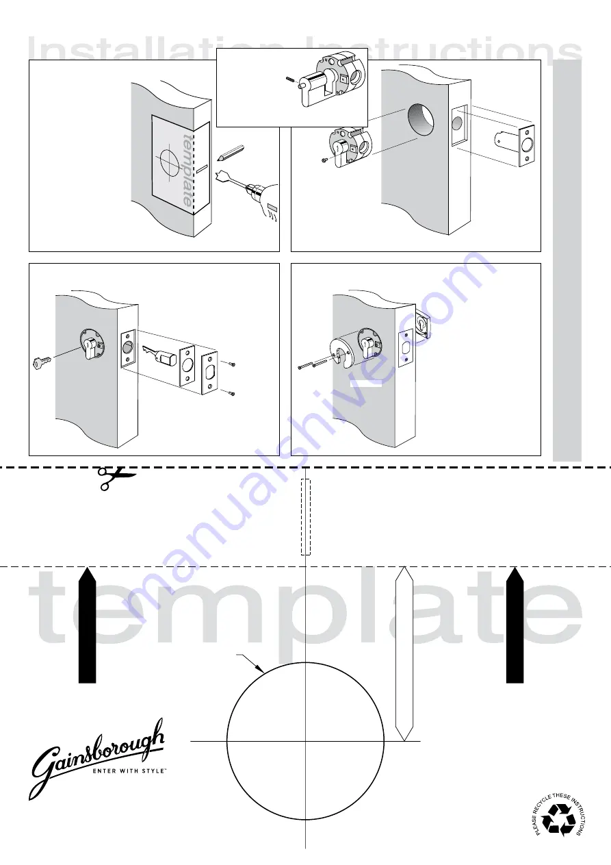
Installation template
for 1851 double
cylinder deadbolts
NOTE:
Carefully follow these instructions when installing.
S
crews to be tightened to a recommended 2.5Nm torque max.
Step 1.
Step 2.
• Mark and chisel latch
faceplate until flush with
door edge. Use latch
carrier as a template.
• Insert lock body into
54mm (2 1/8") hole.
• Insert bolt carrier through 22mm
(7/8") hole into lock body assembly
and fix with 2 screws. Ensure
T-
shape
at rear of bolt carrier is upright
.
54mm (2 1/8") hole
• Fold template where indicated
.
• Position template on door edge
at desired latch height
.
• Firmly hold template and mark
latch height on door edge
and 54mm (2 1/8") lock body
hole centre
.
• Measure door thickness and
mark centre
.
• Drill 22mm (7/8
"
) latch hole
through door edge.
Note:
it is important to drill
this hole squarely
.
•
D
rill pilot hole for lock body
[suggested size 3mm (1/8")].
Then enlarge hole to 54mm
(2 1/8"), drilling from both
sides of the door
.
Step 3.
Step 4.
A
Please Note:
for a single cylinder deadbolt
(ie. with internal turnbutton)
ensure stem A is on
the internal side of the
door. If this is not the
case, rehand lock body
by removing grub-screw with allen key provided,
turn cylinder to desired direction and re-fasten.
• Insert key and rotate towards edge
of the door.
• Insert bolt until stop and rotate key
away from edge of the door.
• If bolt does not operate properly
repeat above steps.
• Install plastic faceplate shim and
faceplate, then screw into position.
• Insert screws through internal
horse shoe & connect to
external square cap.
Note:
do not overtighten
screws.
• Insert key and rotate to check
lock function. Please note that
deadbolt requires 180° key
rotation to achieve
deadlocking.
• If bolt does not operate
properly repeat step 3.
interior side
ORIGINA
TION CRM GSH 853 071
1
Gainsborough Hardware Industries Limited,
Melbourne, Australia. A.B.N. 25 004 792 269
www.gainsboroughhardware.com.au
PA
IT166
JUL ‘11


