CompuScope 3200C
165
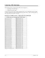
Pin layout on CS3200C connector – Differential, ECL/PECL inputs
CS3200C connector pin layout (Differential, ECL/PECL inputs)
1
CLK+
35
CLK-
2
D0+
36
D0-
3
D1+
37
D1-
4
D2+
38
D2-
5
D3+
39
D3-
6
D4+
40
D4-
7
D5+
41
D5-
8
D6+
42
D6-
9
D7+
43
D7-
10
D8+
44
D8-
11
D9+
45
D9-
12
D10+
46
D10-
13
D11+
47
D11-
14
D12+
48
D12-
15
D13+
49
D13-
16
D14+
50
D14-
17
D15+
51
D15-
18
D16+
52
D16-
19
D17+
53
D17-
20
D18+
54
D18-
21
D19+
55
D19-
22
D20+
56
D20-
23
D21+
57
D21-
24
D22+
58
D22-
25
D23+
59
D23-
26
D24+
60
D24-
27
D25+
61
D25-
28
D26+
62
D26-
29
D27+
63
D27-
30
D28+
64
D28-
31
D29+
65
D29-
32
D30+
66
D30-
33
D31+
67
D31-
34
TRIG IN+
68
TRIG IN-
Input comparators
The input stage for all inputs of the CS3200C is an EMI filter followed by a 50
Ω
terminating resistor network
wide bandwidth analog comparator.
For single-ended input models, one of the inputs to the comparator is the input signal and the other is a
programmable voltage level generated by an on-board DAC (Digital to Analog Converter). This enables the
input stage to handle different voltage level CMOS signals, e.g. 3.3 Volt, 5 Volt etc.
For differential input models, both inputs of the comparator are fed by the two differential signals corresponding
to a particular input. For example, D0+ and D0- are fed into the inputs of the same comparator.
Summary of Contents for CompuScope 85GC
Page 6: ......
Page 24: ...18 Installing CompactPCI PXI Master Slave multi card systems Notes...
Page 30: ...24 Memory organization on CompuScopes except for CS85GC Notes...
Page 75: ...Driver installation guide 69 Help About CsTest...
Page 76: ...70 Driver installation guide Notes...
Page 90: ...84 CompuScope 85GC Notes...
Page 174: ...168 Notes Notes...


