162
CompuScope 3200C
CompuScope 3200C connectors and headers
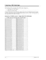
The CompuScope 3200C accepts digital data using a connector designed specially for ultra-fast digital signal
transmission.
A Trigger Out signal is also available on a BNC connector in order to synchronize the CS3200C to the rest of the
test system. The connectors and headers on the CS3200C card are shown below:
Figure 92: Connectors on CS3200C
•
Digital input MDR:
this connector is used to input up to 32 bits of single-ended or differential digital
data lines, one clock input and one trigger input, all with 50
Ω
characteristic impedance.
This connector is designed to provide “equivalent to coax” performance by using copper conductors
encapsulated in a specially formulated Teflon to provide the appropriate dielectric constant. This
assembly is wrapped in a pleated copper foil, resulting in a 50
Ω
transmission line impedance for each of
the 68 conductors in the cable.
For more information on the technology used in this connector, please visit
www.mmm.com
.
•
Trigger Out BNC:
this connector is used to output a 0 to 5 Volt, TTL signal which signifies that a
trigger event has occurred on the CS3200C.
•
Clock Out BNC:
In some select cases, a user may want to drive the rest of the test system with the
internal clock of the CS3200C. A 5 Volt CMOS clock signal capable of driving a 50
Ω
load is available
on the card as a standard feature for this purpose.
Summary of Contents for CompuScope 85GC
Page 6: ......
Page 24: ...18 Installing CompactPCI PXI Master Slave multi card systems Notes...
Page 30: ...24 Memory organization on CompuScopes except for CS85GC Notes...
Page 75: ...Driver installation guide 69 Help About CsTest...
Page 76: ...70 Driver installation guide Notes...
Page 90: ...84 CompuScope 85GC Notes...
Page 174: ...168 Notes Notes...


