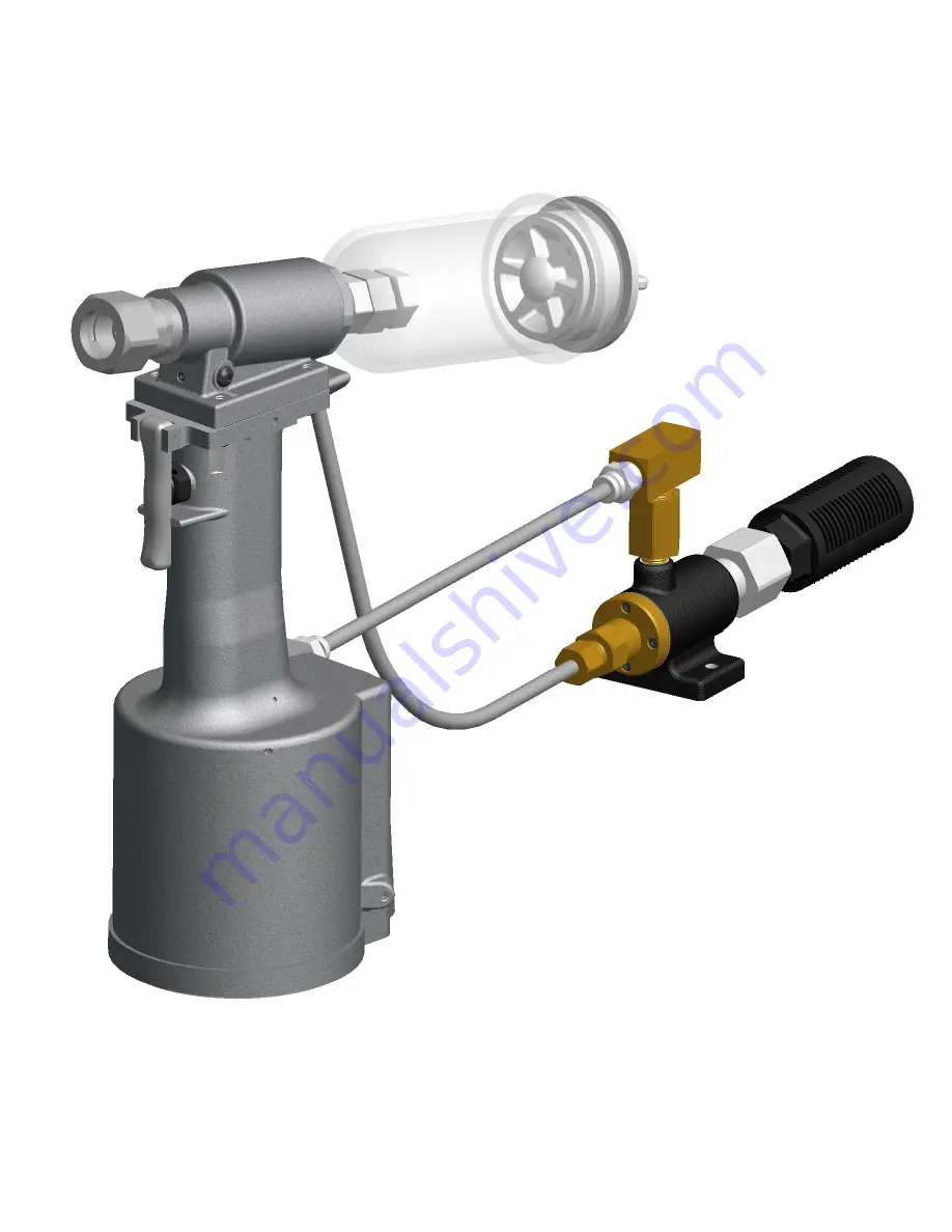
background image

GB751V


INSTALLATION TOOL 

GAGE BILT


MADE IN U.S.A.


GAGE BILT Inc.


44766 Centre Court         (586) 226-1500 

     Clinton Twp. MI 48038     (586) 226-1505 Fax 

        e-mail: [email protected] / www.gagebilt.com


GAGE BILT TOOLS ARE AVAILABLE WORLDWIDE 

E-MAIL US FOR A DISTRIBUTOR NEAR YOU. 

Summary of Contents for GB751V

Page 1: ...GE BILT MADE IN U S A GAGE BILT Inc 44766 Centre Court 586 226 1500 Clinton Twp MI 48038 586 226 1505 Fax e mail solutions gagebilt com www gagebilt com GAGE BILT TOOLS ARE AVAILABLE WORLDWIDE E MAIL US FOR A DISTRIBUTOR NEAR YOU ...

Page 2: ...lent Setting stroke 780 19 8 mm Rated pull load 2 200 lbs 9 8 kN Noise level 81 5 dB A Vibration Tested No Hazards Found TABLE OF CONTENTS Description Page Warnings 3 Principle of Operation 4 How to use the GB751V 5 Description and Maintenance 6 Filling Bleeding 7 Troubleshooting 8 Overhaul 9 Disassembly and Parts Lists 10 11 DEXRON III Oil Safety Data 12 Nose Assembly Selection Chart 13 Warranty ...

Page 3: ...required to use hearing protection A test was carried out in a simulated work environment where the background level was 73 2 dB A In this condition the max level was 81 5 dB A Therefore it is required where prolonged use hearing protection be used CAUTION Do not use beyond the design intent WARNING Tool must be maintained in a safe working condition at all times and examined on a daily basis for ...

Page 4: ...e head cylinder assy causing the piston to move to the rear of the head cylinder assy The internal components of the attached nose assembly are also moving with the piston to start the fastener installation When the fastener installation is completed the actuator lever assy is released Air pressure is then built up inside of the handle assy causing the valve spool assy to return to its original po...

Page 5: ... to use 1 Remove plastic shipping plug from Swivel A 249 and screw in your air fitting 2 Connect air hose to tool 3 8 minimum diameter air line is mandatory 90 p s i 6 2 bar is recommended and cycle tool a few times by depressing and releasing actuator lever assy 704343 Clean dry air is mandatory WARNING Ensure air hose is securely connected to avoid possible hose whipping 3 Disconnect air hose fr...

Page 6: ...l vacuum line if equipped 2 Point nose assembly into oil as shown Fig A 3 Cycle tool 8 10 times and wipe dry MAINTENANCE WARNING Maintenance personnel MUST read and understand all warnings and cautions WARNING Disconnect tool from its power source before performing maintenance WARNING Excessive contact with hydraulic oil and lubricants should be avoided WARNING Dispose of hydraulic oil in accordan...

Page 7: ... after tool has been dismantled and reassembled take the following steps after depressing actuator lever assy AND DISCONNECTING THE AIR SUPPLY 1 Remove four button head cap screws A 928 and head cylinder assy 703109 from handle assy 704132 Slowly push piston 751307 completely forward 2 Fill handle assy 704132 and the oil passage on top of handle assy 704132 with automatic transmission oil Dexron I...

Page 8: ...ed 5 AIR BYPASS FROM VALVE HOUSING a If the spring 704141 breaks or dislodges air will flow freely through the muffler 704146 Replace or reset Valve spring installation tool 704162 is recommended b Check o rings on valve sleeve 704140 valve spool assy 704143 and valve plug 704145 If worn or damaged replace Valve sleeve removal tool 704163 is recommended c 6 FASTENER STEM JAMMED IN NOSE ASSEMBLY a ...

Page 9: ...ntains a complete set of o rings back up rings screws washers and gasket 704214 STEM CATCHER BAG 704149 PISTON ROD WRENCH 704151 POWER CYLINDER TOOL 704152 SEAL GUIDE 704150 PACKING PLUG WRENCH 704153 BLEEDER BOTTLE 704162 VALVE SPRING INSTALLATION TOOL 704163 VALVE SLEEVE REMOVAL TOOL S1178 VALVE EXTRACTOR 704214 CATCHER BAG AS SHOWN ABOVE IS SOLD SEPARATELY Part No Description 704149 Piston Rod ...

Page 10: ... end cap 703114 1 Push against threaded end of piston 751307 to slide it out of head cylinder assy 703109 Be careful not to damage threads or cause burrs on polished piston 751307 surface The re assembly sequence is the opposite of disassembly See Filling and Bleeding instructions Apply Loctite 242 and torque the button head cap screws A 928 uniformly to 40 inch lbs to prevent leakage around the g...

Page 11: ...andle assy 704132 reverse the above procedure being certain that all o rings are properly lubricated before installation Torque packing plug 704118 to 45 foot lbs Attach the seal guide 704152 to the piston rod assy 704138 and tap the piston rod assy 704138 through the packing plug 704118 Attach air piston assy 704121 and flexlock nut 400559 Torque flexlock nut to 40 inch lbs Attach air piston assy...

Page 12: ...ergoes combustion ACCIDENTAL RELEASE MEASURES Protective Measures Eliminate all sources of ignition in vicinity of spilled material Spill Management Stop the source of the release if you can do it without risk Contain release to prevent further contamination of soil surface water or groundwater Clean up spill as soon as possible Use appropriate techniques such as applying non combustible absorbent...

Page 13: ... 752B 20 6C 752B 45 6C 751C 54RA 6C 751 43OS 1 8 3A 352B 25 3A 752C 45 3A 751C 54RA 3A 752A 43OS 5 32 4A 752C 20 4A 752C 45 4A 751C 54RA 4A 752A 43OS 3 16 5A 752C 20 5A 752C 45 5A 751C 54RA 5A 752A 43OS 1 RIGHT ANGLE NOSE ASSEMBLIES MAY REQUIRE MORE THAN ONE PULL 2 INSTALLS 1 8 5 32 3 16 DIAMETERS 3 ALUMINUM ONLY 4 INSTALLS 5 32 3 16 1 4 DIAMETERS NOTE THE LAST 2 DIGITS OF THE NOSE ASSEMBLY REPRES...

Page 14: ... instruction sheets furnished by seller Sellers obligation under this warranty shall be limited to the repair or rework of the goods supplied or replacement thereof at Seller s option and in no case is to exceed the invoice value of said goods Under no circumstances will the seller be liable for incidental or consequential damages or for damages incurred by the buyer or subsequent user in repairin...

Reviews: