background image

11.  ECHO SOUNDER

11-27

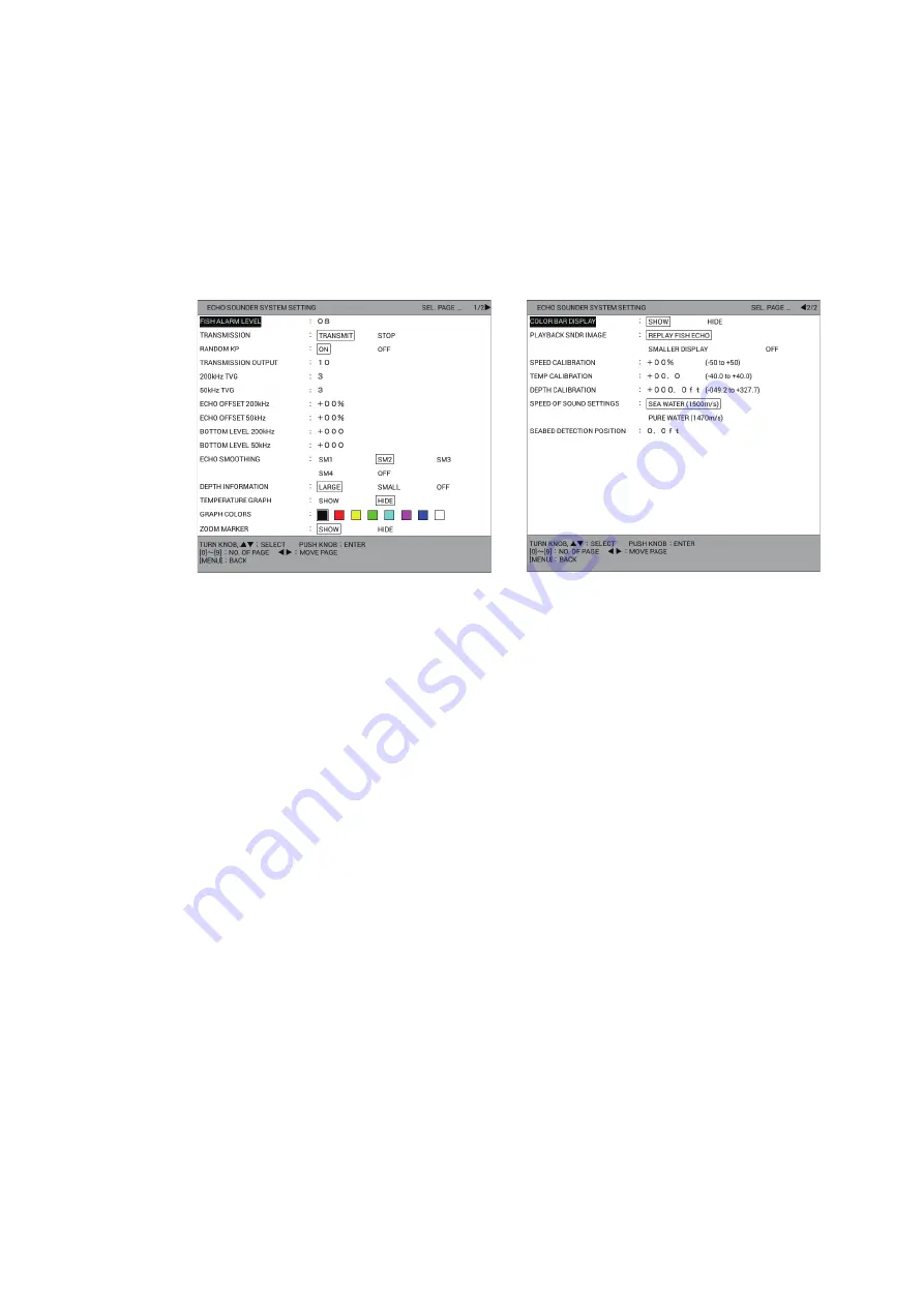
11.18 [ECHO SOUNDER SYSTEM SETTING] Menu

The [ECHO SOUNDER SYSTEM SETTING] menu sets up the functions of the echo 
sounder display.

1. Press the 

MENU

 key to open the main menu.

2. Select [0. SYSTEM SETTING].
3. Select [8. ECHO SOUNDER INITIAL SETTING].
4. Select [1. ECHO SOUNDER SYSTEM SETTING].

5. Set each menu item referring to the following.

[FISH ALARM LEVEL]: Set the echo strength that triggers the fish alarms (setting 
range: 1 to 15, default: 8). Set the smaller value for ice-blue and stronger echoes, 
medium value for yellow and stronger echoes, larger value for red and stronger 
echoes.
[TRANSMISSION]: Turns TX power on or off. [TRANSMIT] enables transmission. 
[STOP] stops transmission.
[RANDOM KP]: To reduce interference caused by the pulse transmission of own 
fish finder, correct the cycle of pulse transmission randomly. Select [ON] to acti-
vate this function.
[TRANSMISSION OUTPUT]: When two or more fish finders are being operated in 
the same vicinity, mutual interference can occur. To reduce the interference, you 
can reduce the transmission power by lowering this setting. To disable this fish 
finder, set this setting to [0] (setting range: 0 to 10, default: 10).
[200kHz TVG], [50kHz TVG]: TVG (Time Varied Gain) compensates for propaga-
tion attenuation of the ultrasonic waves. It does this by equalizing echo presenta-
tion so that schools of fish of the same size appear in the same density in both 
shallow and deep waters. In addition, it reduces surface noise. Note that if the 
TVG level is set too high short range echoes may not be displayed (setting range: 
0 to 9, default: 3).
[ECHO OFFSET 200kHz], [ECHO OFFSET 50kHz]: If the on-screen echo level 
appears to be too weak or too strong and the level cannot be adjusted satisfacto-
rily with the gain control on the display unit, adjust echo offset to compensate for 
too weak or too strong echoes (setting range: -50 to +50%).
[BOTTOM LEVEL 200kHz], [BOTTOM LEVEL 50 kHz]: If the depth indication is 
unstable in automatic operation or the bottom echo cannot be displayed in red-
dish-brown by adjusting the gain control in manual operation, you may adjust the 
bottom echo level detection circuit, for both 50 kHz and 200 kHz, to stabilize the 

Page 1

Page 2

Summary of Contents for GP-3700F

Page 1: ...GPS WAAS COLOR CHART PLOTTER with FISH FINDER GP 3700F OPERATOR S MANUAL www furuno com Model Product Name GPS PLOTTER SOUNDER...

Page 2: ...s manual is elemental chlorine free FURUNO Authorized Distributor Dealer 9 52 Ashihara cho Nishinomiya 662 8580 JAPAN A APR 2017 Printed in Japan All rights reserved Pub No OME 44920 A YOTA GP 3700F 0...

Page 3: ...or service marks of their respective holders How to discard this product Discard this product according to local regulations for the disposal of industrial waste For disposal in the USA see the homep...

Page 4: ...structions before attempting to operate the equipment Indicates a potentially hazardous situation which if not avoided could result in death or serious injury Indicates a potentially hazardous situati...

Page 5: ...ement Name Warning Label 1 Type 86 003 1011 3 Code No 100 236 233 10 Warning Label Do not depend on one navigation device for the navigation of the vessel Always check your position against all availa...

Page 6: ...Satellite status location display 2 4 2 2 How to Use the Cursor 2 5 2 3 How to Change the Chart Scale Zoom In Zoom Out 2 5 2 4 Orientation Mode 2 6 2 5 How to Shift the Display 2 7 2 6 How to Measure...

Page 7: ...w to enter marks at the cursor position 4 4 4 2 3 How to enter marks by manually entering latitude and longitude position 4 4 4 3 How to Enter Lines 4 5 4 4 How to Erase Marks Lines 4 6 4 5 How to Edi...

Page 8: ...9 5 9 2 1 How to set TD display 9 5 9 2 2 How to set range for plotter display 9 8 9 3 DISPLAY FORMAT Menu 9 8 9 4 NAVIGATOR SETUP Menu 9 15 9 5 INPUT OUTPUT PORT SETTING Menu 9 18 9 5 1 How to set t...

Page 9: ...4 Manual Echo Sounder Operation 11 9 11 4 1 How to activate the manual echo sounder mode 11 9 11 4 2 How to select the display range 11 10 11 4 3 How to shift the display range 11 10 11 4 4 How to ad...

Page 10: ...ximity alarm 12 6 12 5 3 How to set the CPA TCPA alarm 12 7 12 5 4 How to set the lost alarm 12 7 12 5 5 How to set the external AIS alarm 12 8 13 MAINTENANCE TROUBLESHOOTING 13 1 13 1 Maintenance 13...

Page 11: ...arks according to the sort conditions Simple drift calculation provides a graphic presentation of surface water flow Alarms Arrival anchor watch XTE border speed trip AIS CPA TCPA temperature shear de...

Page 12: ...g fre quency or lower the transmission sound pressure level for the following equipment in the order shown 1 Wideband fish finder 2 Fish finder with multiple frequencies 3 Fish finder with single freq...

Page 13: ...20 526TID HDD 3 Required for 1 kW transducer 50B 6 50B 6B 200B 5S and 50 200 1T Display Unit GP 3700F Antenna Unit GPA 020S 1 Antenna Unit GPA 021S 2 Event Switch 1 Event Switch 2 External Monitor USB...

Page 14: ...SYSTEM CONFIGURATION xii This page is intentionally left blank...

Page 15: ...emit two beeps If you do not need the key beep deacti vate the beep sound see section 9 3 13 11 10 2 1 3 4 5 6 7 8 9 12 14 15 16 19 20 18 17 21 GOTO DISP CANCEL CENTER WPT SAVE MOB ZOOM IN TM RM MENU...

Page 16: ...oses the main menu With the menu open goes back one layer in selected menu Closes the window 12 Numeric keys 0 to 9 Enters numeric data 1 to 8 Enters corresponding mark labeled on the key Selects menu...

Page 17: ...ic data entry or an operation 3 Scrollwheel Rotate upward Zooms in the chart display range Rotate downward Zooms out the chart display range Push with cursor shown Moves cursor to the screen center in...

Page 18: ...no DGPS beacon receiver Only the beacon receiver equipped GP 3700F has DGPS ca pability To get DGPS capability install the optional internal DGPS beacon receiver name Beacon Receiver Set type OP14 80...

Page 19: ...ress the DISP key consecutively to cycle through all the active displays Displays other than display 1 can be skipped See section 1 4 3 1 4 2 How to change a display s setting Five basic screens are p...

Page 20: ...st differ according to the split pattern selected at step 6 8 Select the display screen from LIST OF DISPLAY SCREENS Note The plotter or compass can be selected as the upper display screen only in the...

Page 21: ...1 4 3 How to skip a display You may not require all five display screens You can skip unnecessary ones as fol lows 1 Press the MENU key to open the main menu 2 Select 0 SYSTEM SETTING 3 Select 4 DISPL...

Page 22: ...t for the NAV information box from the pattern list 6 Select a frame then select the item to display in the frame from the navigation data list Set up other frames similarly The items in the list diff...

Page 23: ...tate the ENTER knob to select a menu item then push the knob to confirm your selection Counterclockwise rotation moves the cursor downward or leftward clockwise rotation moves the cursor upward or rig...

Page 24: ...n 2 Repeat step 1 to select all other characters Delete a character Select or to move the data input cursor to the character deleted then select Delete Suggest feature This unit remembers five of the...

Page 25: ...range and bearing from the own ship position to the MOB position are displayed at the left top of the screen Only one MOB mark can be put on the plotter display and each time the SAVE MOB key is opera...

Page 26: ...n assigned to the F1 key 5 Referring to the table below select a function Function Description WAYPOINT LIST Opens WAYPOINTS LIST ROUTES LIST Opens ROUTES LIST SAVE USB MEMORY Opens the USB MEMORY REC...

Page 27: ...screen FISH FINDER SHIFT Opens the FISH FINDER SHIFT window in the man ual echo sounder mode FISH FINDER DEPTH RANGE Opens the BTM DISP RNG U or L LIM window in the automatic echo sounder mode Opens...

Page 28: ...E 5 Select INTERNAL DEMO 6 Select SPEED SETTING 7 Use the numeric keys to enter speed 8 Select CRS BRG SETTING 9 Use the numeric keys to enter direction 10 Select LATITUDE SETTING 11 Use the numeric k...

Page 29: ...position data D DGPS POSITIONING Use DGPS position data E DEAD RECKONING Use dead reckoning position data M ENTER MANUAL Use manually entered position course etc N NO POSITIONING Use no position data...

Page 30: ...1 OPERATIONAL OVERVIEW 1 16 This page is intentionally left blank...

Page 31: ...2 1 1 Plotter display layout The plotter display shows chart data tracks waypoints marks etc Use it to monitor ship s progress toward a destination NAV information box North mark Orientation mode Cour...

Page 32: ...on 1 4 4 Speed over the ground Course Time Cursor position in latitude and longitude Ship s position in latitude and longitude Example for navigation information no destination set Ship s position in...

Page 33: ...mark shows ship s cross track distance from the intended course The mark is shown in black when the amount of cross track distance is within the XTD monitor range and hollow when it is over An arrow...

Page 34: ...trical field strength of the received signal on the selected frequency The higher the number the stronger the received signal and a figure above 60 is normal SN SN Signal to Noise ratio displays the r...

Page 35: ...15 press and together The procedures in this manual for sake of brevity replace the rotate and press actions with move the cursor When the cursor reaches an edge of the screen the display is scrolled...

Page 36: ...a tion Head up Displays the chart with the current compass heading of own ship at the top of the screen When the heading changes own ship mark remains fixed and the chart picture rotates according to...

Page 37: ...in the direction in which the trackball is rolled 3 Press the CENTER key In north up or specified direction up mode own ship mark is returned to the cen ter of the screen In head up AC up course up or...

Page 38: ...left of the screen 3 Use the trackball to put the cursor on the starting point 4 Push the ENTER knob then the X mark moves to the cursor position 5 Use the trackball to put the cursor on the ending po...

Page 39: ...rossing line cross hair cursor See How to disable unnecessary cursors on page 2 10 Note 2 When the cursor is not displayed the selected cursor can move with the own ship mark 2 For the cursor other th...

Page 40: ...r Circle Select ALL to turn on all cursor configurations 6 Press the DISP key to close the menu How to set the orientation method and the number of parallel index lines 1 Press the MENU key to open th...

Page 41: ...Chart Icons The chart icon at the bottom right of the screen changes according to the state of the chart See the table below The chart scale is displayed on the right side of the icon The scale value...

Page 42: ...2 PLOTTER DISPLAY OVERVIEW 2 12 This page is intentionally left blank...

Page 43: ...ection 6 1 3 3 1 How to Show Hide Track 3 1 1 How to show hide own ship track Own ship track is shown by default 1 Press the MENU key to open the main menu 2 Select 4 MARK TRACK SETTING 3 Select DISPL...

Page 44: ...n the main menu 2 Select 4 MARK TRACK SETTING 3 Select OWN TRACK MAX POINTS on page 1 4 Press the numeric keys to enter the max memory points for own track The fol lowing confirmation message appears...

Page 45: ...SYM BOLS or DISPLAY GPS BUOY SYMBOLS 4 Select SHOW to show each track or symbol or HIDE to hide each track or sym bol 5 Press the DISP key to close the menu 3 1 3 How to show hide the current vector T...

Page 46: ...k memory as follows 1 Press the PLOT INTVL key consecutively so the track plotting interval icon at the bottom of the screen shows hold to stop recording the track Each press of the key selects the tr...

Page 47: ...ck plotting is stopped 5 Press the DISP key to close the menu 3 2 3 How to connect track after restarting plotting When you restart plotting of track the points where the plotting was stopped and re s...

Page 48: ...MP Track color changes with water temperature Requires water temperature sensor 9 WTR DEPTH Track color changes with depth 4 Press the MENU or DISP key to close the window Note You can partly change t...

Page 49: ...y to close the menu How to change track color by temperature variation This setting paints the track in up to five colors according to temperature variation se lected The setting EV 0 2 for example pa...

Page 50: ...COLOR BY DEPTH on page 2 4 Select RANGE 5 Set the depth range as desired For example to change track color to red when the depth is more than 1000 ft do the following 1 Select RED 2 Press the 1 0 0 0...

Page 51: ...on for 10 seconds 3 Select COLOR 4 Press the numeric key corresponding to desired color The color changes at the moment a key is pressed 5 Press the MENU or DISP key to close the window 3 4 How to Cha...

Page 52: ...be comes full the oldest track is erased to make room for the latest 3 5 1 How to select the track plotting method for own ship The own ship track is traced at an interval of time or distance The defa...

Page 53: ...setting range is 00M 00S to 99M 59S for time 0 00 NM to 9 99 NM for range When set TIME IN TERVAL and RANGE INTERVAL to 0 the track is traced at intervals of 1 sec ond 7 Press the DISP key to close t...

Page 54: ...4 Select SEL METH 5 Press the applicable numeric key to select the method for erasing range For 1 BTWN 2PTS or 2 SET RNG go to step 6 For 3 WITHIN RNG 4 OUT OF RNG or 5 ALL go to step 7 6 Do one of th...

Page 55: ...distinguish previous and current track Four methods of selecting range to edit are available 1 BTWN 2PTS Edits all tracks between two points entered on the plotter display Both current track and play...

Page 56: ...selected for editing is displayed in NO OF TRK PTS SEL 11 Select RUN to edit the own ship track you set 12 Press the DISP key to close the menu 3 8 How to Display Own Ship Information 3 8 1 Simple inf...

Page 57: ...ted using the data of COG course over the ground and STW speed through the water The calculated drift is displayed in DRIFT When DISPLAY OS DRIFT VEC TOR on page 5 in the DISPLAY FORMAT menu is set to...

Page 58: ...PS BUOY LIST to display the GPS buoy list Shifts the page or rotation of the ENTER knob Selects a GPS buoy CENTER key Centers the selected GPS buoy on the plotter display When TARGET SMART TRACK is se...

Page 59: ...on 3 4 PLOT INTVL key Stops or restarts recording of track for the selected GPS buoy 4 Press the DISP key to close the GPS buoy list and the menu 3 10 How to Change the Size of the Target Number You c...

Page 60: ...line type selected at step 10 among all recorded tracks for other ships Go to step 7 6 For 1 SPECIFY TARGET select a track point for the target to erase 7 Select COLOR 8 Press the applicable numeric k...

Page 61: ...mark color Marks can be inscribed in seven colors of red yellow green light blue purple blue and white 1 Press the MARK COLOR key to show the CHANGE MARK COLOR window Note This window automatically cl...

Page 62: ...y displayed marks is changed to the size selected here 4 1 3 How to set line type There are four line types 1 Press the MENU key to open the main menu 2 Select 4 MARK TRACK SETTING 3 Select LINE TYPE...

Page 63: ...k at the cursor position Enter a mark by manually entering latitude and longitude position Note A mark can be entered with the symbol or the numeric labeled on the operated numeric key Select the entr...

Page 64: ...1 Press the MENU key to open the main menu 2 Select 5 MARK TRACK EDIT DELETE 3 Select 3 INPUT MARK 4 Select LATITUDE 5 Press the numeric keys to enter the latitude of the mark then push the ENTER kno...

Page 65: ...ict important locations such as fishing spots and danger areas Lines can be connected with marks 1 Press the CURSOR ON OFF key to turn on the cursor 2 Put the cursor on the starting point for the line...

Page 66: ...ory that are set to YES on ADD MARK LINE DISP in the DISPLAY INTERNAL MEMORY menu see section 10 2 2 cannot be erased How to erase individual marks lines on the screen 1 Press the CURSOR ON OFF key to...

Page 67: ...marks of all shapes and figures within the area you set 11 Select TYPE 12 Select the fish type to erase WITHOUT Erases marks without fish type ALL Erases any mark having fish type The number of targe...

Page 68: ...shape or figure Select NO CHANGE to keep the previous shape 11 Select LINE TYPE 12 Press the applicable numeric key to select the new line type Select 5 NO CHANGE to keep the previous line type 13 Se...

Page 69: ...ing a mark at own ship position see section 4 2 1 you can take a screenshot then display it on the mark information window To take a screen shot do the following 1 Press the MENU key to open the main...

Page 70: ...ow to turn on or off an object to filter on page 4 12 3 Rotate the ENTER knob to select content to filter The marks of selected object and content to filter are displayed on the screen Object for filt...

Page 71: ...ing depth more than 328 ft display marks with depth 16 ft of the set ting When 0 0 ft minimum is set displays marks with depth below 0 0 ft When 656 ft maximum is set displays marks with depth above 6...

Page 72: ...are turned on when pushing the ENTER knob See step 2 at How to set object and content for the mark filter on page 4 10 How to set the fish type for the mark filter You can set the option of content fo...

Page 73: ...EEK FRM 30DAYS FRM 1 YEAR THIS TERM THIS TIME AA AA TO BB BB AA AA TO NOW THIS TERM Displays marks of plus or minus one month from the current date re gardless of year THIS TIME Displays marks of plus...

Page 74: ...4 MARKS LINES 4 14 This page is intentionally left blank...

Page 75: ...ran A LOP Enter a waypoint by Decca LOP Waypoints can be entered from the echo sounder display 5 1 1 How to enter waypoints at own ship position 1 Press the SAVE MOB key The following message appears...

Page 76: ...of the screen as the icon default circle in red Note 1 The waypoint icon may not be shown at the bottom right of the screen depend ing on the menu setting If it is not shown you can show it as follows...

Page 77: ...nt then push the ENTER knob To switch the coordinate from North to South and vice versa use the CUR SOR ON OFF key 9 Select LONGITUDE 10 Press the numeric keys to enter the longitude of the waypoint t...

Page 78: ...e intrusion ban alarm radius is other than 0 00 NM the waypoint marks on the plotter display and the waypoint list become auto matically For how to set the intrusion point alarm see section 8 5 21 Sel...

Page 79: ...the procedure from step 11 in section 5 1 3 5 1 5 How to enter waypoints by Loran A or Loran C LOPs 1 Press the MENU key to open the main menu 2 Select 8 PLOTTER DISPLAY SETTING 3 Select 3 LORAN DECCA...

Page 80: ...procedure from step 11 in section 5 1 3 5 1 6 How to enter waypoints by Decca LOPs 1 Press the MENU key to open the main menu 2 Select 8 PLOTTER DISPLAY SETTING 3 Select 3 LORAN DECCA SETTING 4 Select...

Page 81: ...int to edit The EDIT WPT NAME window appears Note 1 Waypoints can be sorted by alphanumeric order distance to own ship mark type or registration order see section 5 4 Note 2 A waypoint s color or shap...

Page 82: ...Press the DISP key to close the menu 5 4 How to Search Waypoints You can search waypoints by sort method alphanumeric order distance to own ship mark type registration order or waypoint name How to s...

Page 83: ...ip s speed Go to step 7 ENT VALU Calculate TTG with manually entered speed Go to step 6 6 Press the numeric keys to enter speed TTG for the selected waypoint is calculat ed using the speed entered her...

Page 84: ...or HIDE LARGE Waypoints are shown in actual mark shape SMALL Waypoints are shown with an x regardless of mark shape selected HIDE All waypoints are turned off except the waypoint destination and route...

Page 85: ...ds to create a route With existing waypoints With track based route using own ship positions recorded at preset intervals With selected track of own ship or other ship 6 1 1 How to create routes with...

Page 86: ...t list The preview for the selected waypoint is displayed at the bottom right of the screen When 11 or more waypoints are registered use or to switch the page Waypoints are sorted in order of the sele...

Page 87: ...have a maximum of 100 points For automatic entry you need to set an interval of time or distance This feature is useful when you wish to retrace a track The SAVE icon appears at the bottom right of th...

Page 88: ...the DISP key to close the menu 6 1 3 How to create routes with selected tracks You can create routes with the selected tracks of own ship or other ships 1 Press the MENU key to open the main menu 2 Se...

Page 89: ...used route numbers 13 Press the DISP key to close the menu 6 2 How to Edit Routes 6 2 1 How to insert waypoints You can newly insert waypoints to a registered route 1 Press the MENU key to open the ma...

Page 90: ...e then press the CANCEL key The following message appears 5 Select RUN to delete the route 6 Press the DISP key to close the menu 6 4 How to Search Routes You can search routes by sort method alphanum...

Page 91: ...the Speed to Use in TTG Calculation Calculation of TTG is based on ship s speed data Speed can be set manually or au tomatically 1 Press the MENU key to open the main menu 2 Select 1 ROUTES WAYPOINTS...

Page 92: ...6 ROUTES 6 8 This page is intentionally left blank...

Page 93: ...s having the same numbers as newly entered ones are written over How to select the quick point entry method You can select the quick point entry method single point or multiple points up to 100 points...

Page 94: ...destination information range and bearing from own ship to the destination ETA and TTG to the destination appear on the NAV information box The location is saved to the waypoints list under the name...

Page 95: ...nect between other waypoints The line shows the shortest course to the destination Arrows on the line show the direction to follow to get to the destina tion When selecting DISTANCE TO WAYPOINT BEARIN...

Page 96: ...p with the destination When selecting DIS TANCE TO WAYPOINT and BEARING TO WAYPOINT for destination information range and bearing from own ship to the destination appear on the NAV information box How...

Page 97: ...as destinations are registered on the waypoint log To set a waypoint among these waypoints as the destination do the following When the waypoint log memory becomes full the oldest waypoint is erased...

Page 98: ...s in SET AS DEST 6 Press the DISP key to close the menu A light blue line connects the own ship with the first destination and green dotted lines connect between other waypoints When selecting DISTANC...

Page 99: ...witches the waypoint to the next sequen tial waypoint when the vessel enters the arrival alarm area or the vessel passes an imaginary perpendicular line passing through the center of the destination w...

Page 100: ...7 DESTINATION 7 8 7 4 How to Stop Navigation 1 Press the GOTO key to show the following message 2 Select RUN to stop navigation XXXXXX SET AS A DESTINATION CANCEL DESTINATION RUN CANCEL...

Page 101: ...uzzer sounds and the alarm icon appears For the alarms of fish normal fish bottom lock fish in dividual and bottom discrimination see section 11 17 Note When multiple alarms occur violated alarm types...

Page 102: ...or dis able the audio alarm as follows 1 Press the MENU key to open the main menu 2 Select 6 ALARM SETTINGS 3 Select ALARM PATTERN on page 1 4 Select the audio alarm type SHORT BEEP Three beeps sound...

Page 103: ...a orange dashed circle marks the anchor watch area 1 Press the MENU key to open the main menu 2 Select 6 ALARM SETTINGS 3 Select ARRIVAL ALARM or ANCHOR WATCH ALARM on page 1 4 Select ON 5 Select ALA...

Page 104: ...DISP key to close the menu To deactivate an alarm select OFF at step 4 8 4 XTE Border Alarm The XTE cross track error alarm warns you when your vessel is off its intended course When the XTE alarm is...

Page 105: ...n the main menu 2 Select 6 ALARM SETTINGS 3 Select INTRUSION POINT ALM on page 1 4 Select ON 5 Press the DISP key to close the menu To deactivate an alarm select OFF at step 4 8 6 Ship Speed Alarm The...

Page 106: ...s the MENU key to open the main menu 2 Select 6 ALARM SETTINGS 3 Select TRIP RANGE RESET on page 1 to show the following message 4 Select RUN to reset the trip range 5 Press the DISP key to close the...

Page 107: ...4 8 9 Shear Alarm The shear alarm which requires a water temperature sensor sounds when the water temperature goes higher or lower than the preset value within the interval time set 1 Press the MENU k...

Page 108: ...2 Select 6 ALARM SETTINGS 3 Select DEPTH ALARM on page 3 4 Select ON 5 Select STARTING DEPTH 6 Press the numeric keys to enter the start depth setting range 0 to 4000 ft 7 Select WIDTH 8 Press the nu...

Page 109: ...key to open the main menu 2 Select 7 COAST LINE SETTING 3 Select 1 COAST LINE DETAIL SETTING which has three pages 4 Select an item to change 5 Select an option 6 After setting all required items pres...

Page 110: ...ge 1 to TIDAL STATION on page 2 when selecting SHOW Displays no navigation data regardless of each setting when selecting HIDE LIGHT BEACONS LIGHT BUOYS BUOY CONTOUR LINES TIDAL CURRENT Turns each mar...

Page 111: ...NICS Navigational chart data by Navionics Select this when using Navion ics chart data FISHING EQUIP MENT SEABED COMPO SITION WATER QUALITY ALARM AREA MOUNTAINTOP LANDSCAPE FOG SIGNAL SIGNALS SERVICE...

Page 112: ...nce between the contour lines 1 Press the MENU key to open the main menu 2 Select 7 COAST LINE SETTING 3 Select 2 CONTOUR LINE FINE RNG SETTINGS 4 Select the range which you want to display in detail...

Page 113: ...ct 3 LORAN DECCA SETTING 4 Select LORAN A STA COMB 5 Press the numeric keys to set the station combination referring to the CH CODE LIST at the bottom of the window If necessary follow the procedure f...

Page 114: ...the window 6 Press the numeric keys to set the chain station combination from RCH CODE LIST at the bottom of the window If necessary follow the procedure from step 7 to enter offset Otherwise go to s...

Page 115: ...ress the numeric keys to enter offset To switch between and press the CUR SOR ON OFF key 9 Enter offset for OFFSET VALUE 2 in the same way 10 Select TIME DIFF DISP TYPE 11 Select DECCA 12 Press the DI...

Page 116: ...8 PLOTTER DISPLAY SETTING 3 Select 5 PLOTTER RANGE SETTING 4 Select the range to change 5 Select ON or OFF 6 Press the DISP key to close the menu 9 3 DISPLAY FORMAT Menu The DISPLAY FORMAT menu contai...

Page 117: ...re data For details see the installation manual DEPTH SENSOR Selects the source of depth data from NMEA or FISH FINDER For details see the installation manual NMEA DEPTH OFFSET An offset may be applie...

Page 118: ...earing is a bearing measured using true North as the ref erence direction and it is calculated by the formula True Bearing Magnetic Bearing Magnetic Variation Magnetic bearings are measured with magne...

Page 119: ...course to that destination Range and bearing are calculated by the Great Circle or Rhumbline method Route total distance is also calculated Cross track dis tance is only calculated in the Rhumbline me...

Page 120: ...LENGTH SHIP S WIDTH ANTENNA POSITION V a and ANTENNA POS SIDE b below SHIP S LENGTH Sets the ship s length See the installation manual SHIP S WIDTH Sets the ship s width See the installation manual AN...

Page 121: ...section 2 2 CURSOR COLOR Selects the color of the cursor from seven colors DISPLAY OWN SHIP Turns the own ship data on or off When SHOW is selected place the cursor on the own ship mark to show the ow...

Page 122: ...t number 10 Note 1 If the selected ship moves off the screen it is automatically moved to the screen center Note 2 Press the CENTER key twice to move the own ship to the screen center ENTER MOB Select...

Page 123: ...al time enter the time difference between local time and UTC time Use the CURSOR ON OFF key to switch from to and vice versa The setting range is 13 30 to 13 30 NMEA TIME DIFFERENCE If the NMEA time d...

Page 124: ...ical chart The L L offset icon appears at the bottom right of the plotter display DISABLE SATELLITE GPS Every GPS satellite is broadcasting abnormal satellite number s in its Almanac which contains ge...

Page 125: ...shown below Select AUTO MATIC or MANUAL depending on the satellite No AUTOMATIC Automatically search for the GEO satellite within your current position Satellite No 120 Longitude range 35 75 W to 25 5...

Page 126: ...of the screen in the Spec ified direction up mode See section 2 4 COURSE SMOOTHING During position fixing ship s course is directly measured by receiving GPS satellite signals The raw course data may...

Page 127: ...ted LAT LON FORMAT Selects the number of minute places to shown in latitude and longitude position from hundredth thousandth or ten thousandth OUTPUT WAYPOINT Select ON to output the WPL and RTE sente...

Page 128: ...Select 0 SYSTEM SETTING 3 Select 5 INPUT OUTPUT PORT SETTING 4 Select 7 ETHERNET SETTING 5 Select IP ADDRESS 6 Use the numeric keys to enter the IP address 7 Select SUBNET MASK 8 Use the numeric keys...

Page 129: ...elow is displayed in SET for the pri ority sensor in USE for the currently used sensor 6 Press the DISP key to close the menu 9 5 4 How to set the NMEA2000 PGN 1 Press the MENU key to open the main me...

Page 130: ...tion 13 8 the memory and user data clearing see section 13 9 9 6 1 How to set or change the password You may use a password to prevent unauthorized operation of the equipment The equipment cannot be o...

Page 131: ...disable the password do the following 1 Press the MENU key to open the main menu 2 Select 0 SYSTEM SETTING 3 Select 6 TEST MEMORY CLEAR 4 Select 7 DISABLE PASSWORD 5 Select RUN 6 Press the DISP key t...

Page 132: ...e cur sor moves without human intervention because of hull vibration increase this set ting to lessen trackball sensitivity to vibration Note A large setting can affect cursor response because minute...

Page 133: ...ise go to step 9 5 Connect a USB flash memory to the USB port see section 10 3 1 The indication NO USB at the top of the screen changes to STOPPED SAVING 6 Push the ENTER knob to save the log data The...

Page 134: ...9 OTHER FUNCTIONS 9 26 This page is intentionally left blank...

Page 135: ...ween the working memory and internal memory 10 2 1 How to save the data to the internal memory Data in the working memory can be saved to the internal memories Up to 30 000 track points for own ship 4...

Page 136: ...ow the COM MENT window The current date is automatically named as the comment To change the comment go to the next step Otherwise go to step 9 8 Enter the comment up to 15 characters see How to enter...

Page 137: ...TRCK CONS or ADD MARK LINE DISP in the internal memory block you want to load The memory capacity and the number of currently recorded data are displayed to the right of each item 5 Select YES 6 Repea...

Page 138: ...data can not be added if the memory capacity is reached 30 000 For REC OWN TRK or REC OTHR TRK the oldest data is erased to make room for the latest For ex ample when 25 000 track points for own ship...

Page 139: ...ORY ENTRIES The following confirmation message appears 5 Select RUN to delete the data 6 Press the DISP key to close the menu 10 3 USB Flash Memory Operations Note Keep water away from the unit when t...

Page 140: ...e saved to a USB flash mem ory 1 Connect a USB flash memory in the USB drive 2 Press the MENU key to open the main menu 3 Select 3 USB INTERNAL MEMORY MANAGEMENT 4 Select 1 USB MEMORY RECORDING 5 Sele...

Page 141: ...4 How to play back the data from the USB flash memory Data in the USB flash memory can be loaded to the working memory and played back on the screen However loaded waypoint route and setting data will...

Page 142: ...r data 8 Select SEL DATUM 9 Select WGS 84 or TOKYO 10 Select the file to replay from DATA SELECTION The message LOAD FILE ARE YOU SURE THE SYSTEM WILL REBOOT WHEN THE FILE IS LOAD ED appears 11 Select...

Page 143: ...rks lines routes waypoints and set ting data automatically when turning the power on There are two backup methods Automatic backup by a USB flash memory Automatic backup by the internal memory Note Th...

Page 144: ...ckup the data manually There are two manual backup methods Backup by a USB flash memory Backup by the internal memory How to backup the data to a USB flash memory manually 1 Connect a USB flash memory...

Page 145: ...e 2 Press the MENU key to open the main menu 3 Select 3 USB INTERNAL MEMORY MANAGEMENT 4 Select 9 LOADING BACKUP DATA 5 Select 1 LOAD FROM USB MEMORY The following message appears 6 Select RUN to load...

Page 146: ...AVED SCREENSHOT appears Note Do not operate any keys until the message disappears 3 Connect a USB flash memory in the USB drive 4 Press the MENU key to open the main menu 5 Select 3 USB INTERNAL MEMOR...

Page 147: ...h the data to load are saved in the USB drive 2 Press the MENU key to open the main menu 3 Select 3 USB INTERNAL MEMORY MANAGEMENT 4 Select IMPORT EXTERNAL DATA Note 2 GD x80 FLOPPY and 7 GD 188 FLOPP...

Page 148: ...ile to load from DATA SELECTION The confirmation message ap pears 12 Select RUN to load the data The message TRANSFERRING PLEASE WAIT appears Note It may take approx 20 minutes to transfer the data ac...

Page 149: ...vertical scan lines Each line is a picture of the objects under the boat The series of pictures are put side by side across the screen to show the contours of the bottom and echoes from fish The amou...

Page 150: ...r the frequency of the ultrasonic signal the bet ter the resolution For this reason the 200 kHz frequency is ideal for detailed observation of schools of fish In this chapter the combination of VRM an...

Page 151: ...mpare the same picture with two different sounding frequencies 11 2 3 Marker zoom display 50 kHz or 200 kHz The marker zoom display expands a selected area of the normal echo sounder picture on the le...

Page 152: ...ock display 50 kHz or 200 kHz The bottom lock display provides a normal picture on the right half of the screen and a 2 to 10 meters 7 to 30 feet wide layer in contact with the bottom is expanded on t...

Page 153: ...ong echo tail means a hard bottom 11 2 7 A scope display 50 kHz 200 kHz or dual frequency The A scope display shows echoes at each transmission with amplitudes and tones proportional to their intensit...

Page 154: ...ween low and high frequencies and displays echoes from tiny fish in discriminative colors This is done by utilizing the fact that tiny fish return a stronger echo against a high frequency rather than...

Page 155: ...lit Plotter display or echo sounder display single frequency is displayed on the left half or right half of the screen Three way split Plotter display is displayed on the upper left or right of the sc...

Page 156: ...select FISHING at the fishing ground 11 3 1 How to select an automatic echo sounder mode 1 Press the MENU key to open the main menu 2 Select 9 ECHO SOUNDER SETTING 3 Select 1 AUTO to show the AUTO wi...

Page 157: ...the setting window for high frequency press the GAIN key again Note The AUTO GAIN OFFSET window closes automatically when there is no operation for 10 seconds 2 Set an offset value setting range 5 to...

Page 158: ...r a different function default setting FISH FINDER DEPTH RANGE 11 4 3 How to shift the display range The shift function determines the start depth of the picture Start depth shift is shown at the top...

Page 159: ...frequency display select the frequency to adjust by pressing the GAIN key then go to step 2 2 Set the gain to show a slight amount of noise on the screen setting range 0 to 10 0 0 5 step 3 Press the G...

Page 160: ...this time the track cursor appears on the ship s track line of the plotter display and it denotes the approximate geographical position of the time marker 2 Operate the trackball to place the time mar...

Page 161: ...play Plotter echo sounder display When the cursor is turned on a vertical line is entered at the time marker position of the echo sounder display On the plotter display the selected mark or number is...

Page 162: ...R SETTING 3 Select 3 CLUTTER 4 Set the clutter rejection level The larger the setting value the greater the degree of suppression Set the level to 0 when no clutter exists to prevent erasure of weak e...

Page 163: ...or in white For example you may want to display the bottom echo in white to discriminate fish echoes near the bottom 1 Press the MENU key to open the main menu 2 Select 9 ECHO SOUNDER SETTING 3 Select...

Page 164: ...gain setting or display color 5 Press the DISP key to close the menu 11 11 Display Colors You can select the number of colors and background color to use as follows 1 Press the MENU key to open the m...

Page 165: ...eys to set the color brightness for R red G green or B blue of new color referring to the color samples setting range 0 to 15 The larg er the number the brighter the color 8 Repeat step 6 and step 7 t...

Page 166: ...number of scan lines made per transmission For example 2 1 creates two scan lines per one transmission and is the fastest advance speed 1 16 creates one scan line per 16 transmissions and is the slowe...

Page 167: ...ounterclockwise to scroll the past picture clockwise to scroll back to the current picture SMALLER DISPLAY The compressed entire past picture appears 2 Push the ENTER knob to ease the past picture and...

Page 168: ...the transmission line cannot be detected see section 11 19 This feature cannot be used with the transducer installed inside the hull Depending on the transducer frequency fish may not be detected Fur...

Page 169: ...0 to 100 7 Press the DISP key to close the menu 11 15 3 How to select the display mode to show fish information 1 Press the MENU key to open the main menu 2 Select 0 SYSTEM SETTING 3 Select 8 ECHO SOU...

Page 170: ...n a colorful graphic display A transducer or triducer that supports the bot tom discrimination display is required There are two bottom discrimination displays GRAPHIC and DETAILS GRAPHIC The most pro...

Page 171: ...ture uses the range from the ship s draft therefore enter the ship s draft How to set up bottom discrimination display Note Automatic range is automatically turned on when the bottom discrimination di...

Page 172: ...sounds For audio alarm type see section 8 1 Note 1 When multiple alarms occur violated alarm types alternately appear at the bottom of the display Note 2 The fish alarm bottom lock is available only...

Page 173: ...a fish echo is within a predetermined dis tance from the bottom which makes it useful for detecting fish close to the bottom This alarm is available for the bottom lock display Note that the sensitiv...

Page 174: ...u To disable the alarm select OFF at step 4 11 17 4 Bottom discrimination alarm The bottom discrimination seabed composition alarm sounds when the bottom type rock gravel sand mud matches both the bot...

Page 175: ...uce the interference you can reduce the transmission power by lowering this setting To disable this fish finder set this setting to 0 setting range 0 to 10 default 10 200kHz TVG 50kHz TVG TVG Time Var...

Page 176: ...ED CALIBRATION Applies an offset to the speed data See the installation manual TEMP CALIBRATION Applies an offset to the water temperature data See the installation manual DEPTH CALIBRATION In the def...

Page 177: ...you how to set custom ranges for basic range section 11 4 2 zoom range marker and bottom zoom section 11 2 3 and section 11 2 4 and bottom lock range section 11 2 5 Note All basis ranges 1 to 8 zoom...

Page 178: ...o es timate density of a school of fish fish specifies and hardness of the bottom The background color can be selected on the menu see section 11 11 Minute mark The minute mark displays a minute worth...

Page 179: ...cause of the difference in travel time at both edges of the beam angle For the rough bottom echoes are reflected on many different planes which displays echoes in many layers giving a 3D effect Nature...

Page 180: ...propagates and a school of fish in deep water is displayed larger Density of school of fish If two schools appear with the same color at different depths the one in deeper water is denser because the...

Page 181: ...d wa ter temperatures meet a current rip occurs A current rip ap pears on the screen as shown in the right illustration Surface noise When the sea is rough or the ship moves over a wake surface noise...

Page 182: ...oise As shown in the figure below unwanted signals are displayed cyclically or at random The source of these unwanted signals may be induction from electrical machinery ship s vibration engine noise i...

Page 183: ...redrawn after the head ing is changed in the head up mode How to show AIS symbols 1 Press the MENU key to open the main menu 2 Select 4 MARK TRACK SETTING Symbol Status Remarks Sleeping target Denote...

Page 184: ...rom being identified Dangerous tar gets cannot be slept To activate or sleep targets do the following 1 Press the CURSOR ON OFF key to turn on the cursor 2 Put the cursor on the target you wish to act...

Page 185: ...ack All AIS symbols and tracks are displayed in the selected color from now 5 Select LINE TYPE 6 Select the line type for the AIS track AIS tracks are displayed with the selected line type from now 7...

Page 186: ...ata 1 Press the CURSOR ON OFF key to turn on the cursor 2 Put the cursor on the target you wish to display its data then push the ENTER knob to show the detailed AIS target data 3 Press the MENU or DI...

Page 187: ...lternately For an AIS target the indication shown in the figure below appears at the top left of the screen Note The orientation mode for own ship can not be changed during OS MODE ENTER knob Press th...

Page 188: ...gets they might prevent important radar and AIS displays from being identified In this case the targets whose speeds are slower than set with MAX SPD FOR MOORED will not be automatically activated by...

Page 189: ...main menu 2 Select 6 ALARM SETTINGS 3 Select CPA TCPA ALARM on page 2 4 Select ON 5 Select CPA ALARM RANGE 6 Press the numeric keys to set the alarm range setting range 0 1 to 99 9 NM 7 Select TCPA AL...

Page 190: ...AIS alarm The external AIS alarm alerts you when something is wrong with the connected AIS unit 1 Press the MENU key to open the main menu 2 Select 6 ALARM SETTINGS 3 Select EXTERNAL AIS ALARM on page...

Page 191: ...ergent Squeeze the cloth dry then clean the display When the display is clean gently wipe the display with a clean soft dry cloth to prevent scratching Antenna unit Loosened and corroded bolts Tighten...

Page 192: ...rsor moves abnormally ask your dealer about replacement of the trackball See section 13 4 about trackball maintenance 13 4 Trackball Maintenance If the cursor moves abnormally clean the trackball and...

Page 193: ...leshooting Symptom Remedy You cannot turn on the power Check for blown fuse Check that the power connector is firmly fastened Check for damaged power cable Check battery for proper voltage output Pres...

Page 194: ...a points true north always Check the course by displaying the AIS target data see section 12 4 1 Symptom Remedy Picture does not move al though marks and characters appear Check that the picture advan...

Page 195: ...0 SYSTEM SETTING 3 Select 0 MAINTENANCE 4 Select 1 UNIT INFORMATION 5 Select 1 MAIN 2 GPS 3 BEACON an internal beacon receiver required 4 FISH FINDER or 5 DATABASE 6 Push the ENTER knob to close a wi...

Page 196: ...rred stopped 1 Press the MENU key to open the main menu 2 Select 0 SYSTEM SETTING 3 Select 0 MAINTENANCE 4 Select 4 OPERATION ALARM LOG 0 to 9 keys Enter the page number on SEL PAGE to show the page d...

Page 197: ...hecked using a dedicated connector at the factory are normally displayed as NG Note 2 The test result of LAN WIRED CAN USB FRNT or USB BACK is displayed as NG without connection to each port 1 Press t...

Page 198: ...is functioning correctly if its on screen location fills in light blue when the knob is pushed Each push switches light blue and white alter nately Rotate the ENTER knob clockwise to increase the valu...

Page 199: ...rks waypoints and routes or all screenshot data 13 9 1 How to restore the settings 1 Press the MENU key to open the main menu 2 Select 0 SYSTEM SETTING 3 Select 6 TEST MEMORY CLEAR 4 Select 4 MEMORY C...

Page 200: ...ta 1 Press the MENU key to open the main menu 2 Select 0 SYSTEM SETTING 3 Select 6 TEST MEMORY CLEAR 4 Select 9 CLEAR USER DATA to show the following message 5 Select RUN to delete the user data The m...

Page 201: ...2 USB MEMORY REC OWN TRK ADD NO PLAYBACK REC OTHR TRK ADD NO RECORD MARK TRACK OVERWRITE ADD NO RECORD ROUTE WPT OVERWRITE NO SEL DATUM WGS 84 TOKYO LOAD SETTING OVERWRITE NO 3 INTERNAL REC OWN TRK Y...

Page 202: ...TOR SHOW HIDE DISP STOPPED TRACKS SHOW HIDE PLOT STOPPED TRACKS DRAW TRACK LINE NO TRACK LINE OWN TRACK MAX POINTS 100 to 30000 30000 TRACK COLOR BY TEMP RANGE EV 0 2 EV 2 0 DISPLAY BELOW ITEMS WITH W...

Page 203: ...urple 6 Blue 7 White 8 ALL SHAPE 1 2 3 4 5 6 7 8 1 2 3 4 5 6 7 8 9 0 ALL TYPE WITHOUT ALL RUN 3 INPUT MARK LATITUDE Enter latitude LONGITUDE Enter longitude COLOR 1 Red 2 Yellow 3 Green 4 Light blue 5...

Page 204: ...ED 0 1 to 99 9 kn 1 0 kn AIS PROXIMITY ALARM ON OFF ALARM RANGE 0 1 to 99 9 NM 1 0 NM CPA TCPAALARM ON OFF CPAALARM RANGE 0 1 to 99 9 NM 1 0 NM TCPAALARM RANGE 1 to 99M 59S 30S AIS LOST ALARM ON OFF L...

Page 205: ...STATION SHOW HIDE CHANGE CHARTS VECTOR FISHING C MAP NAVIONICS 2 CONTOUR LINE FINE RNG SETTINGS 0 025 NM to 1024 NM 0 to 4 0 3 INDIVIDUAL CONTOUR LINE SETTINGS 8 PLOTTER 1 SATELLITE STATUS LOCATION SA...

Page 206: ...PILOT NMEA0183 NMEA2000 AUTOMATIC SEL BEARING SENSOR NMEA0183 NMEA2000 AUTOMATIC HEADING OFFSET 180 to 180 0 SBAS SET BY SC USE DO NOT USE BEARING OFFSET 180 to 180 0 PITCH OFFSET 90 to 90 0 ROLL OFFS...

Page 207: ...ND BLACK ON WHITE BACKGROUND WHITE ON BLACK BACKGROUND GREEN ON BLACK BACKGROUND EVENT SWITCH 1 NONE ENTER MOB SCREEN SHOT INPUT MARK EVENT SWITCH 2 NONE ENTER MOB SCREEN SHOT INPUT MARK POP UP MESSAG...

Page 208: ...Hz A SCOPE SINGLE DISP 200kHz MARKER ZOOM DUAL DISP 200kHz BOTTOM ZOOM DUAL DISP 200kHz BOTTOM LOCK DUAL DISP 200kHz BOTTOM DISC DUAL DISP 50kHz 200kHz VERT DUAL DISPLAY 50kHz 200kHz DUAL DISP A SCOPE...

Page 209: ...TRANSMIT STOP SETTING RANDOM KP ON OFF TRANSMISSION OUTPUT 0 to 10 10 200kHz TVG 0 to 9 3 50kHz TVG 0 to 9 3 ECHO OFFSET 200kHz 50 to 50 0 ECHO OFFSET 50kHz 50 to 50 0 BOTTOM LEVEL 200kHz 100 to 100 0...

Page 210: ...5 to 4000 ft RANGE 1 15 ft RANGE 2 30 ft RANGE 3 60 ft RANGE 4 120 ft RANGE 5 200 ft RANGE 6 400 ft RANGE 7 1000 ft RANGE 8 1500 ft ZOOM RANGE 15 to 400 ft 30 ft BOTTOM LOCK RANGE 7 to 30 ft 30 ft 0 M...

Page 211: ...an waypoint State of chart left suitable chart scale middle unsuitable chart scale right no chart file Shape of mark left numeral right graphic Latitude and longitude position offset applied Track is...

Page 212: ...AP 12 APPENDIX 3 TIME DIFFERENCES...

Page 213: ...de Area Augmentation System Europe EGNOS Euro Geostationary Navigation Overlay Service Japan MSAS Multi Functional Satellite Augmentation System India GAGAN GPS And GEO Augmented Navigation These four...

Page 214: ...ERR Your vessel is off its intended course see section 8 4 Check course and adjust as nec essary INTRUSION Your vessel crosses the area defined by the two waypoints see section 8 4 Check course and a...

Page 215: ...A fish echo is within the preset alarm range see section 11 17 1 BTM FISH A fish echo is within a predetermined distance from the bottom see section 11 17 2 SNGL FSH A fish of the specified length is...

Page 216: ...approx 95 of the time 2 drms 2 5 Tracking velocity 999 kn 2 6 Position fixing time 90 s approx 2 7 Position update interval 1 s 2 8 Beacon receiver internal kit option Frequency range 283 5 to 325 0 k...

Page 217: ...istinction 4 5 Auto mode Cruising Fishing selected 4 6 Picture advance 6 steps 5 INTERFACE 5 1 Number of ports IEC61162 1 NMEA 3 ports NMEA0183 V1 5 2 0 3 0 4 1 4800 38400 bps LAN 1 port Ethernet 100B...

Page 218: ...AL CONDITIONS 7 1 Ambient temperature Antenna unit 25 C to 70 C Display unit 15 C to 55 C 7 2 Relative humidity 93 or less 40 C 7 3 Degree of protection Antenna unit IP56 Display control unit IP22 7 4...

Page 219: ...Bottom zoom display 11 4 Brilliance 1 4 C Character display 9 1 Chart icons 2 11 Chart scale 2 5 Chart type 9 3 Clutter 11 14 Color bar 11 28 11 30 Compass display 2 3 Controls Display unit 1 1 Track...

Page 220: ...ype 4 2 Line monitor 9 24 Loading data from other equipment 10 13 Log operation alarm 13 6 LOP formula 9 7 Loran A 9 5 Loran C 9 5 M Magnetic bearing offset 9 10 Main menu overview 1 9 Maintenance 13...

Page 221: ...13 Ship s length 9 12 Ship s width 9 12 Simple calculation of drift 3 15 Single frequency display 11 2 Sound speed 11 28 Speed averaging 9 16 Speed calibration 11 28 Speed sensor 9 9 Speed smoothing 9...

Page 222: ...ze 5 10 searching 5 8 speed for TTG calculation 5 9 Waypoint name display 9 2 Waypoint status 9 12 Weak echoes erasing 11 14 White line 11 16 White marker 11 15 X XTE alarm 8 4 Z Zero line 11 30 Zero...

Page 223: ...kl rung ist unter der folgenden Internetadresse verf gbar K esolevaga deklareerib Furuno Electric Co Ltd et lalmainitud raadioseadme t p vastab direktiivi 2014 53 EL n uetele Pilns ES atbilst bas dekl...

Page 224: ...m o wiadcza e wy ej wymieniony typ urz dzenia radiowego jest zgodny z dyrektyw 2014 53 UE Pe ny tekst deklaracji zgodno ci UE jest dost pny pod nast puj cym adresem internetowym O a abaixo assinado a...

Reviews: