2. WIRING
2-17
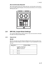
How to mark the input voltage label
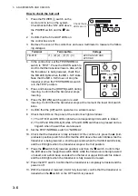
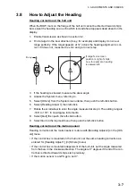
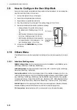
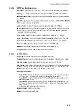
After setting toggle switches and changing the fuses, mark the label on the inside of
the cover with the voltage that applies. In the example shown below, 100 V is checked;
20A fuses are used.
2.9
DIP SW, Jumper Block Settings
This sonar has DIP switches and jumper blocks in the control unit and IF unit that set
the system according to expected usage.
2.9.1
Control Unit
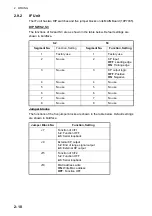
DIP SW1
DIP SW1 is located on the KEY2 Board (10P7033) and it functions as shown in the
table below. Default settings are shown in boldface. For use of optional No.2 control
unit, see .
Segment No.
Function, Setting
1
Function of control unit
OFF
: Main control unit
ON
: Sub control unit
2
No use
3
No use
4
No use
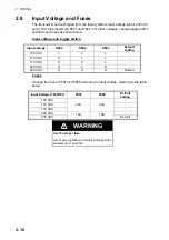
FUSE FUSE
F601 F602
INPUT
(TB-B101)
FUSE
F601 F602
100V
110V 20A 20A
115V
220V
230V
10A 10A
Summary of Contents for FSV-85
Page 28: ...1 HOW TO INSTALL THE SYSTEM 1 20 This page is intentionally left blank ...
Page 56: ...3 ADJUSTMENTS AND CHECKS 3 10 This page is intentionally left blank ...
Page 67: ...12 Nov 2010 Y NISHIYAMA D 1 ...
Page 68: ...4 Feb 2011 Y NISHIYAMA D 2 ...
Page 69: ...5 Nov 2010 Y NISHIYAMA D 3 ...
Page 70: ...4 Apr 2014 H MAKI D 4 ...
Page 71: ...6 Jul 2012 Y NISHIYAMA D 5 ...
Page 72: ...Nov 22 06 T Matsuguchi D 6 ...
Page 73: ...22 Apr 2013 Y NISHIYAMA D 7 ...
Page 74: ...22 Apr 2013 Y NISHIYAMA D 8 ...
Page 75: ...26 Nov 2010 Y NISHIYAMA D 9 ...
Page 76: ...27 Dec 2010 Y NISHIYAMA D 10 ...
Page 77: ...Nov 22 06T Matsuguchi D 11 ...
Page 78: ...D 12 ...
Page 79: ...29 Mar 2011 Y NISHIYAMA D 13 ...
Page 80: ...13 Sep 2011 Y NISHIYAMA D 14 ...
Page 81: ...13 Sep 2011 Y NISHIYAMA D 15 ...
Page 82: ...Mar 14 07 R Esumi D 16 ...


