2. WIRING
2-6
2.4
IF Unit
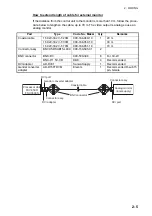
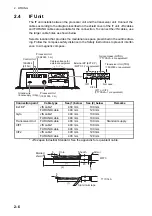
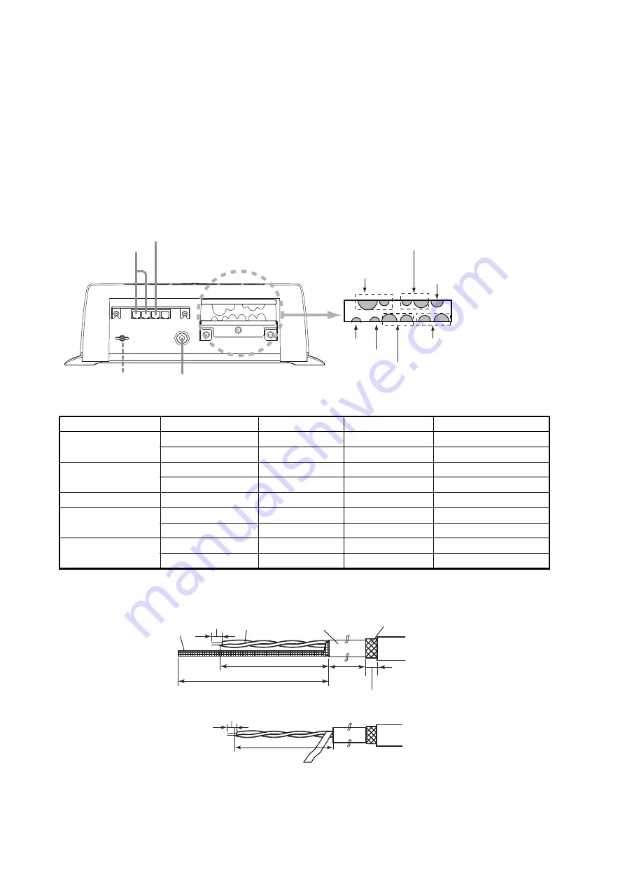
The IF unit installs between the processor unit and the transceiver unit. Connect the
cables according to the diagram inscribed on the shield cover of the IF unit. JIS cables
and FURUNO cables are available for the connection. To connect the JIS cables, use
the larger cable holes as shown below.
Select a location that provides the maintenance space prescribed in the outline draw-
ing. Follow the compass safety distance in the Safety Instructions to prevent interfer-
ence to a magnetic compass.
*: JIS=Japan Industrial Standard. See the appendix for equivalent cable.
Connection point
Cable type
See (1) below
See (2) below
Remarks
Ext. KP
JIS cable*
400 mm
100 mm
FURUNO cable
400 mm
120 mm
Gyro
JIS cable*
400 mm
100 mm
FURUNO cable
400 mm
100 mm
Transceiver Unit
FURUNO cable
400 mm
100 mm
Standard supply
CIF1
JIS cable*
400 mm
100 mm
FURUNO cable
400 mm
100 mm
CIF2
JIS cable*
400 mm
120 mm
FURUNO cable
400 mm
120 mm
Control Unit
Cable entrance for
external equipment
Processor Unit
(19S1050, 3 m)
Processor Unit
(10S2383, 3 m)
10S2884
(5/10 m)
Ground wire
(local supply, IV-2sq)
Gyrocompass (GYRO)
䋨
TTYCSLA-4 or equivalent
䋩
Transceiver Unit (TRX)
䋨
10S2380 or equivalent
䋩
External KP (EXT KP)
䋨
MPYC-12 or equivalent
䋩
CIF1
CIF2
Not used.
CIF1 or CIF2
(TTYCSLA-1 or equivalent)
45
5
(1)
(2)
5
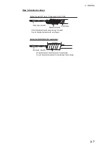
Braided
shield
Core
Sheath
Armor
5
Aluminium tape
㪫㪫㪰㪚㪪㪣㪘
㪤㪧㪰㪚
(1)
Summary of Contents for FSV-35
Page 22: ...1 HOW TO INSTALL THE SYSTEM 1 16 This page is intentionally left blank ...
Page 55: ...D 1 13 Sep 2011 Y NISHIYAMA ...
Page 56: ...D 2 13 Sep 2011 Y NISHIYAMA ...
Page 57: ...D 3 5 Nov 2010 Y NISHIYAMA ...
Page 58: ...D 4 Y Hatai ...
Page 59: ...23 Apr 2013 Y NISHIYAMA D 5 ...
Page 60: ...23 Apr 2013 Y NISHIYAMA D 6 ...
Page 61: ...D 7 13 Sep 2011 Y NISHIYAMA ...
Page 62: ...D 8 13 Sep 2011 Y NISHIYAMA ...
Page 63: ...13 Sep 2011 Y NISHIYAMA D 9 ...
Page 64: ...13 Sep 2011 Y NISHIYAMA D 10 ...
Page 65: ...13 Sep 2011 Y NISHIYAMA D 11 ...
Page 66: ...D 12 13 Sep 2011 Y NISHIYAMA ...

