3. ADJUSTMENTS
3-5
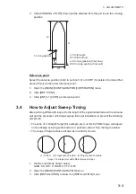
1. Select a stationary target echo at a range between 0.125 and 0.25 NM, preferably
near the heading line.
2. Operate the
EBL
control to bisect the target echo.
3. Read the target bearing.
4. Measure the bearing of the stationary target on the navigation chart and calculate
the difference between the actual bearing and apparent bearing on the radar
screen.
5. Open the [MAIN]>[CONFIGURATION] menu.
6. Click [INSTALLATION] to show the [INSTALLATION] menu.
7. Click [6 HD ALIGN], and enter the bearing difference measured at step 4. The set-
ting range is 0 to 359.9 degrees.
8. Confirm that the target echo is displayed at the correct bearing on the screen.
3.7
How to Suppress Main Bang
If main bang appears at the screen center, suppress it as follows.
1. Transmit the radar on a long range and then wait 10 minutes.
2. Adjust gain to show a slight amount of noise on the display.
3. Select the 0.125 NM range, and adjust STC and RAIN.
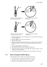
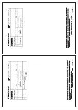
Target
Correct
bearing
relative to
heading
Displayed
position
Target
Displayed
position
Correct
bearing
relative to
heading
Antenna mounting error toward port
(fast timing of heading switch)
Image appears deviated clockwise
(Positive error)
Antenna mounting error toward port
(fast timing of heading switch)
Image appears deviated clockwise
(Positive error)
Summary of Contents for FR-1908V-BB
Page 2: ...Installation Manual This page is intentionally left blank...
Page 6: ...EQUIPMENT LISTS iv This page is intentionally left blank...
Page 14: ...1 MOUNTING 1 8 This page is intentionally left blank...
Page 30: ...3 ADJUSTMENTS 3 8 This page is intentionally left blank...
Page 40: ...11 Dec 2018 H MAKI D 1...
Page 41: ...D 2 2 Nov 2017 H MAKI...
Page 42: ...D 3 2 Nov 2017 H MAKI...

