


1. OPERATIONAL OVERVIEW
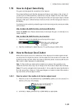
1-34
1.22
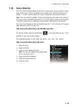
Interference Rejector
Mutual radar interference can occur in the vicinity of an-
other shipborne radar operating in the same frequency
band. It is seen on the screen as a number of bright
spikes either in irregular patterns or in the form of usu-
ally curved spoke-like dotted lines extending from the
center to the edge of the picture. Activating the interfer-
ence rejector circuit can reduce this type of interfer-
ence. The interference rejector is a kind of signal
correlation circuit. It compares the received signals over
successive transmissions and reduces randomly occur-
ring signals. There are three levels of interference rejection depending on the number
of transmissions that are correlated.
You can access this feature from the InstantAccess bar
™
, or from the menu. The avail-
able settings are: [OFF], [1], [2] or [3].
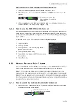
How to reject interference from the InstantAccess bar
To adjust the interference rejector, select the [IR] button (
) on the InstantAc-
cess bar
™
, then left-click to cycle through the rejection levels.
The available settings, in cyclic order, are: [OFF]
o
[1]
o
[2]
o
[3]
o
[OFF]...
Level [3] provides the highest level of rejection.
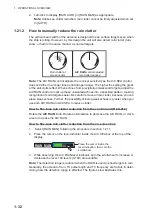
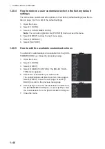
How to reject interference from the menu
1. Open the menu.
2. Select [1 ECHO].
3. Select [2 CUSTOMIZED ECHO].
Note:
You can also right-click the [PICTURE]
box to access this menu.
4. Select [2 INT REJECTOR].
5. Select the required setting.
6. Close the menu.
TM
IR
OFF
Summary of Contents for FAR-2218
Page 132: ...1 OPERATIONAL OVERVIEW 1 110 This page is intentionally left blank ...
Page 176: ...3 TARGET TRACKING TT 3 36 This page is intentionally left blank ...
Page 202: ...4 AIS OPERATION 4 26 This page is intentionally left blank ...
Page 232: ...5 VIDEO PLOTTER OPERATION 5 30 This page is intentionally left blank ...
Page 294: ......