


1. OPERATIONAL OVERVIEW
1-14
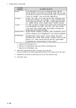
*
1
: Shown on A/B/W-types only
*
2
: Shown on B/W-types only
*
3
: Shown on A/B/W-types only when [5 AUTO TARGET TRACK], located in [2
MARKS] ([2 MARKS•CHARTS] for systems with Radar Plotter functionality)
o
[7
TRACKS]
o
[3 TARGET TRACK] menu, is set to [OFF].
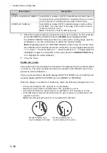
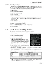
1.8
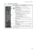
Cursor Data
The cursor data display shows the cursor’s latitude and longitude position or the cur-
sor’s X-Y co-ordinates.
Place the cursor on the [CURSOR DATA] box at the top-right side of the display then
press the
left button
to switch between display formats.
The data box shows the cursor location, bearing/range to the cursor location and the
time to go (TTG) to the cursor location.
Note 1:
For the X-Y co-ordinates display, the Y-axis is the upper/lower half of the
screen, the upper half of the screen is “plus” and the lower part of the screen is “mi-
nus”. The X-axis is the left/right-side of the screen, right is “plus”, left is “minus”.
Note 2:
Cursor data reads "- - -.-" when the cursor is placed outside the operational
display area.
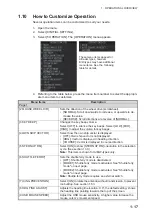
Page 2
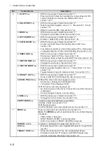
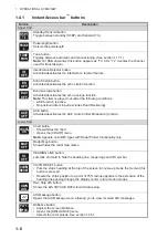
TARGET DATA / ACQ SETTING
Change target tracking settings.
TARGET CANCEL SETTING
Change target cancel settings.
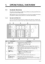
Menu Item
Description
33°59.156’N
135°06.328’E
X: +1.667NM
Y: +3.694NM
TTG 00:05
33°59.156’N
135°06.328’E
0.24.4ºR
4.028NM
TTG 00:05
Bearing/range
displayed
Cursor’s X-Y
co-ordinates
displayed
Press the
left button
to switch between
display formats
Press the
left button
to switch between
display formats
TTG to cursor position
Bearing/range to
cursor position.
X/Y axis
coordinates
to cursor
position.
Cursor positon’s
latitude/longitude
Summary of Contents for FAR-2218
Page 132: ...1 OPERATIONAL OVERVIEW 1 110 This page is intentionally left blank ...
Page 176: ...3 TARGET TRACKING TT 3 36 This page is intentionally left blank ...
Page 202: ...4 AIS OPERATION 4 26 This page is intentionally left blank ...
Page 232: ...5 VIDEO PLOTTER OPERATION 5 30 This page is intentionally left blank ...
Page 294: ......