background image

%%

1

&

'

0

1

6

;

2

'

%2

⇛ޓޓ

1

7

6.

+0

'

ฬޓޓ⒓

0

#/'

ᢙ㊂

3 6;

↪ㅜ㧛஻⠨

4

'

/#

4-

5

⇟ภ

01

&'

5%

4

+2

6+

1

05

+0

56

#.

.#6

+1

0/

#6

'4+

#.

5

#6:

౐ⷺ㩘

㩨㩣㩎

*':

$1.6

/

:

575

%1&'01

⇛࿑

ߩ

ߪ

ޔෳ

ߢ

ߔޕ

ޓ

&

+

/

'

0

5

+

1

0

5

+

0

&

4

#

9

+

0

)

(

1

4

4

'

(

'

4

'

0

%

'

1

0

.

;

㨁㧾

ޓ㧱

㨀㧾

ޓ

㧯㧻

ޓ

㧸㨀

߇

ߩ

ޔ

ߦ

ߢ

޽

ޔ

ߤ

ߜ

߆

߇

ߞ

ߡ

޿

߹

ߔ

ޕ

ޓ

ߥ

߅

ޔ

ߪ

߹

ߖ

ޕ

6

9

1

6

;

2

'

5

#

0

&

%

1

&

'

5

/

#

;

$

'

.

+

5

6

'

&

(

1

4

#

0

+

6

'

/

6

*

'

.

1

9

'

4

2

4

1

&

7

%

6

/

#

;

$

'

5

*

+

2

2

'

&

+

0

2

.

#

%

'

1

(

6

*

'

7

2

2

'

4

2

4

1

&

7

%

6

3

7

#

.

+

6

;

+

5

6

*

'

5

#

/

'

%/#

A

-1

%%

1

&

'

0

1

6

;

2

'

%2

⇛ޓޓ

1

7

6.

+0

'

ฬޓޓ⒓

0

#/'

ᢙ㊂

3 6;

↪ㅜ㧛஻⠨

4

'

/#

4-

5

⇟ภ

01

&'

5%

4

+2

6+

1

05

+0

56

#.

.#6

+1

0/

#6

'4+

#.

5

#6:

&5

౐ⷺ㩘

㩨㩣㩎

*':

$1.6

/

:

575

%1&'01

ዉ㔚

㩍㨺㩖㩩

5*+'

.&+0)

6#2'

64

.

%1&'01

⇛࿑

ߩ

ߪ

ޔෳ

ߢ

ߔޕ

ޓ

&

+

/

'

0

5

+

1

0

5

+

0

&

4

#

9

+

0

)

(

1

4

4

'

(

'

4

'

0

%

'

1

0

.

;

㨁㧾

ޓ㧱

㨀㧾

ޓ

㧯㧻

ޓ

㧸㨀

߇

ߩ

ޔ

ߦ

ߢ

޽

ޔ

ߤ

ߜ

߆

߇

ߞ

ߡ

޿

߹

ߔ

ޕ

ޓ

ߥ

߅

ޔ

ߪ

߹

ߖ

ޕ

6

9

1

6

;

2

'

5

#

0

&

%

1

&

'

5

/

#

;

$

'

.

+

5

6

'

&

(

1

4

#

0

+

6

'

/

6

*

'

.

1

9

'

4

2

4

1

&

7

%

6

/

#

;

$

'

5

*

+

2

2

'

&

+

0

2

.

#

%

'

1

(

6

*

'

7

2

2

'

4

2

4

1

&

7

%

6

3

7

#

.

+

6

;

+

5

6

*

'

5

#

/

'

%/#

A

-2

Summary of Contents for DS-60

Page 1: ...Proof Box option 1 19 1 7 Remote Controller RD 501 Dimmer Controller RD 502 option 1 21 1 8 Rate of Turn Gyro DS 670 option 1 22 2 WIRING 2 1 2 1 Distributor Unit DS 610 2 2 2 2 DIPSW S3 Settings 2 5 2 3 How to Adjust the Analog Indicator 2 6 2 4 Transceiver Unit DS 620 2 7 2 5 Display Unit DS 600 Remote Controller RD 501 Dimmer Controller RD 502 option 2 8 2 6 Junction Box option 2 10 2 7 Rate of...

Page 2: ...nual is elemental chlorine free FURUNO Authorized Distributor Dealer 9 52 Ashihara cho Nishinomiya 662 8580 JAPAN A MAR 2010 Printed in Japan All rights reserved F JUN 16 2016 Pub No IME 72640 F GREG DS 60 0 0 0 1 7 2 3 3 8 1 5 ...

Page 3: ...ts Moderate and stable in temperature and humidity Do not install the unit in a place subject to rain or water splash Fire or electrical shock can result WARNING Indicates a potentially hazardous situation which if not avoided could result in death or serious injury CAUTION Indicates a potentially hazardous situation which if not avoided may result in minor or moderate injury Warning Caution Manda...

Page 4: ...31 A Exposed to the weather Protected from the weather by waterproof container DS 600 DISPLAY UNIT MAIN DISPLAY UNIT RD 501 REMOTE CONTROLLER RD 502 DIMMER CONTROLLER RD 50 RD 20 IEC 61162 Output x 5 IEC 61162 Input x 3 Distance Run Pulse x 4 Alarm System External KP KP Output 100 240 VAC Analog Voltage Output x 1 Analog Meter Output x 2 Analog Current Output x 1 RD 50 RD 20 DS 600 DS 610 DS 620 D...

Page 5: ...0A 631A Tank with flange Type 66 027 7002 DS 660A N For DS 630A 631A Tank without flange DS 660A S For DS 630A 631A Tank with sleeve Type 66 027 7301 Gate Valve DS 661 1 For DS 630 only Select one Installation Material CP26 01501 001 081 900 1 set For DS 600 CP66 01701 001 082 190 1 set For DS 610 CP66 01702 001 082 290 1 set For DS 620 CP66 01703 001 082 630 1 set For DS 630 CP66 01740 000 016 37...

Page 6: ... DS 640 1 w installation materials CP66 01721 DS 645A B 1 Waterproof Box DS 605 R 000 016 398 1 w installation materials CP66 01731 right hand open door DS 605 L 000 016 727 1 w installation materials CP66 01731 left hand open door Flange OP66 6 000 016 400 1 For DS 660 Tightening Handle OP66 7 001 082 950 1 Remote Controller RD 501 000 016 197 1 Dimmer Controller RD 502 000 016 198 1 Analog Indic...

Page 7: ...nstallation location that is well ventilated Locate the display unit where shock and vibration are minimal Allow enough maintenance space at the sides and rear of the display unit and leave enough slack in cables to facilitate maintenance and servicing Observe the compass safe distances see page i to prevent the interference to a mag netic compass The nominal viewing distance for the display unit ...

Page 8: ...wing for details Hanger assembly Type OP26 8 Code No 000 016 313 00 1 Remove the hanger mounting plate from the hanger assembly 2 Fasten the hanger mounting plate to the display unit from the left side and right side with four binding head screws M5x12 3 Make a four pilot holes for self tapping screws 5x20 in the mounting location 4 Fix the hanger to the mounting location with four self tapping sc...

Page 9: ...it to be used as a sub display attach the alarm lid supplied as ac cessories to the ALARM ACK key to prevent accidental operation of the key 260 5 10 24 288 5 11 34 240 9 45 279 5 10 98 51 5 2 01 149 5 87 91 3 58 240 9 45 Fixing hole 4 7 190 0 5 7 48 75 0 5 2 95 40 Set cosmetic cap to hole so cap is flush with panel ALARM Alarm lid assy For sub display only Attach the double sided tape to the reve...

Page 10: ...eave space around the unit for maintenance and checking Refer to the drawing at the back of this manual for minimum recommended maintenance space A magnetic compass will be affected if the transceiver unit is placed too close to it Observe the compass safe distances to prevent disturbance to the magnetic com pass page i Use four hex bolts M10x20 to fix the transceiver unit to the mounting area See...

Page 11: ...s strong enough to support the weight under the continued vibration normally encountered on the vessel A magnetic compass will be affected if the distribution box is too close Observe the compass safe distances to prevent disturbance to the magnetic compass 1 Screw in lower hex bolts so there is 5 mm clearance between bottom of screw head and bulkhead 2 Hang the unit on the bolts then tighten the ...

Page 12: ...at least 2 m from the transducer of an echo sounder Separate as far as possible from air bubble sources e g side thruster and water disposal pipes Install in close proximity to the keel for uniform water flow Generally best performance is obtained by mounting on the bow the stern side is influenced easily by air bubbles and propeller cavitation Do not apply any paint to the transducer face Visuall...

Page 13: ...draft DS 660 Tank top view 3 Weld the tank 2 to the ship s hull The doubling and welding methods are left up to the shipyard 4 Paint the tank 2 flange 4 and fixing plate 5 the same color as the ship s body The tank 2 is pre painted with zinc rich primer The flange 4 and fixing plate 5 are pre painted with zinc rich primer and anti corrosion coat BANNOH 500 If necessary re move it with the sandblas...

Page 14: ...ansducer cable 2 Fix the grommet attached at step 1 to the notch shown below by using the cable fixing plate 17 hex bolt M6x12 18 spring washer M6 19 3 Pass the connector at the end of the transducer cable between the transducer and M16 bolt and attach the notch as shown below 4 Connect the cable assy supplied to the connector attached at step 3 Clean the connector faces and pins before the connec...

Page 15: ...d 6 washer 7 and gasket 8 through the transducer cable DS 631 cable assy and slide them to the white line on the cable 12 Pass the cable through the hole at the top of the tank 2 Metal fixing Hex bolt M6x20 Spring washer M6 Cable assy White line printed on the cable Fixing gland 6 Washer 7 The hollow side must be upward Gasket 8 Tank 2 Transducer cable ...

Page 16: ...sducer tank sectional view 14 Rotate the fixing flange 4 twice horizontally to make two loops These loops make it easy to put the cable in the tank 15 Use the bolt M10x25 9 and spring washer M10 10 to fasten the fixing flange 4 to the tank 2 less than 15 mm Fixing gland Tank Transducer cable M10x25 hex bolt 9 M10 spring washer 10 Rotate the fixing flange 4 twice horizontally to make two loops on t...

Page 17: ... height is necessary For details see the installation drawing at the back of this manual 1 When your unit is shipped assembled remove the five items shown below Gate valve 2 Spacer 3 Gasket 5 2 pcs Shaft 6 1 2 5 17 18 5 17 18 19 6 7 8 24 23 25 4 3 26 27 22 13 12 11 21 20 15 14 10 9 16 Gasket 2 5 Gasket 1 5 Spacer 3 Gate valve 2 Shaft 6 Fore Aft line ...

Page 18: ...ip s body Paint only gray colored areas for other part seal with a masking tape 6 Pass the cable from the transducer 1 through the shaft 6 from the bottom 7 Apply liquid gasket supplied on the top of the transducer 1 8 Use hex bolt 26 and seal washer 27 to fasten the transducer 1 to the shaft 6 9 Pass the gasket 8 flat washer 7 and fixing gland 11 through the transducer cable 10 Fasten the fixing ...

Page 19: ...e stud bolt of the spacer 3 15 Apply grease supplied to both sides of the gasket 2 5 and set it on the gate valve 2 16 Use hex nut 17 spring washer 18 and hex bolt 19 to mount the seachest cap 4 of the shaft 6 on the gate valve 2 17 Move the shaft 6 upward and downward by hands to check if it moves smoothly Gasket 1 5 Apply grease to both sides Spacer 3 Gate valve 2 Apply grease to the inside M20 ...

Page 20: ... at step 4 to stud bolt on the seachest cap The distance between the seachest cap 4 and flange 7 must be 5 mm How to open the gate valve When you open or close the gate valve unfasten two nuts shown below to rotate the handle Then fasten nuts to fix the handle M12 hex nut 20 M12 spring washer 21 M12 flat washer 22 Fore mark at the bottom of the transducer 5 mm Flange 7 Seachest cap 4 ...

Page 21: ...methods are left up to the shipyard 4 Paint the tank 2 flange 4 and fixing plate 5 the same color as the ship s body The tank 2 is pre painted with zinc rich primer The flange 4 and fixing plate 5 are pre painted with zinc rich primer and anti corrosion coat BAN NOH 500 If necessary re move it with the sand blast then paint the flange 4 and fix ing plate 5 the same color as the shipÅfs body 5 For ...

Page 22: ...ixing gland 6 washer 7 and gasket 8 through the transducer cable DS 631A cable assy and slide them to the white line on the cable 7 Pass the cable through the hole at the top of the tank 2 Metal fixing Hex bolt M6x20 Spring washer M6 Cable assy White line printed on the cable Fixing gland 6 Washer 7 The hollow side must be upward Gasket 8 Tank 2 Transducer cable ...

Page 23: ...sducer tank sectional view 9 Rotate the fixing flange 4 twice horizontally to make two loops These loops make it easy to put the cable in the tank 10 Use the bolt M10x25 9 and spring washer M10 10 to fasten the fixing flange 4 to the tank 2 less than 15 mm Fixing gland Tank Transducer cable M10x25 hex bolt 9 M10 spring washer 10 Rotate the fixing flange 4 twice horizontally to make two loops on th...

Page 24: ...e emitting electrical machinery for example electric gen erator radio transmitter and TV Do not install the junction box in place of high temperature and humidity See the outline drawing at the back of this manual Dimensions for DS 640 Dimensions for DS 645A B 200 1 7 87 120 1 4 72 220 1 8 66 233 9 17 7 0 28 6 0 24 5 0 20 5 0 20 10 0 39 12 R2 5 R2 5 7 0 28 200 1 7 87 220 1 8 66 9 1 1 1 2 0 3 5 2 1...

Page 25: ...affected if the waterproof box is too close to the mag netic com pass Observe the compass safe distances see page i to prevent inter ference to a magnetic compass Mounting procedure Note Mount the DS 605 on the bulkhead so the cable glands and the drain hole are down 1 Fix the DS 605 on the wings of the bridge 1 Insert the seal washer 03 001 3002 0 ROHS to four fixing holes 2 Fix the DS 605 with f...

Page 26: ...r 2 3 Remove each binding head screw from four cor ners of the DS 605 and set the DS 600 to the DS 605 These screws can be discarded 4 Apply silicon grease to the binding head screws included in CP66 01731 and fix the DS 600 to the DS 605 with four binding head screws 5 Tighten the clamping glands to fix the cables 6 Apply putty to the cable glands for waterproofing 7 Connect the ground terminal f...

Page 27: ...ler RD 501 and dimmer controller RD 502 can be flush mounted in a panel The size and the mounting procedure are shared by RD 501 and RD 502 For the mounting location refer to the mounting considerations for the dis play unit in section 1 2 Note Before you fasten the display unit to the cutout first connect the cables referring to chapter 2 1 Make a cutout in the mounting location 88 mm width x 76 ...

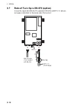
Page 28: ...urn gyro wear the earth strap to prevent the elec trification Use the four stud bolts flat washers spring washers and eight adjust nuts to fix the unit See the outline drawing at the back of this manual Use the XH connector supplied with DS 670 to connect cables Leveling adjustment This adjustment must be performed while the ship is in dry dock where it has no heel ing and trimming inclinations Pl...

Page 29: ...ntenna cable or radio equip ment Locate the DS 60 cables away from the power cables mentioned below Also sep arate cables at least 40 cm when the cables are run parallel with power cables Cable carrying more than a few kilowatts power to fluctuating loads Cable carrying switching waves generated by thyristor etc TTYCYS 4 or TTYCS 4 Max 150 m Distributor DS 610 Display Unit main DS 600 Remote Contr...

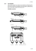
Page 30: ...h unit and connect each cable core to the WAGO connector See the interconnection diagram at the back of this manual The terminal opener is attached inside each unit 2 1 Distributor Unit DS 610 The Distributor Unit DS 610 has two lines of cable clamps and there are 13 cable en trances in total The cables and corresponding cable entrances are shown on the re verse side of the top cover of the DS 610...

Page 31: ...6 5 4 3 2 1 5 4 3 2 1 7 6 5 4 3 2 1 9 8 7 6 5 4 3 2 1 10 9 8 7 6 5 4 3 2 1 14 13 12 11 10 9 8 7 6 5 4 3 2 1 12 11 10 9 8 7 6 5 4 3 2 1 13 12 11 10 9 8 7 6 5 4 3 2 1 8 7 6 5 4 3 2 1 DPYCY 2 5 Power DPYCY 4 Power for DS 620 DPYC 1 5 LOG OUTPUT TTYCY 4S DS 620 640 645A TTYCS 1 IEC61162 IN TTYC Y S 4 Main display TTYCS 1Q Analog meter TTYCS 1 Analog OUT TTYC 7S ALARM TTYCS 1 IEC61162 OUT TTYCS 1 KP IN...

Page 32: ...70 7 TB8 ALARM TTYC 7S 200 7 TB9 IEC61162 OUT TTYCS 1 200 7 TB10 Sub display TTYCS 4 TTYCYS 4 for DS 605 250 7 80 220 7 80 80 50 TB101 Power main DPYCY 2 5 3 Vinyl tape TB5 DS670 S66 9 5 250 7 50 100 5 3 100 Vinyl tape Vinyl tape Vinyl tape Vinyl tape 3 100 6 100 100 100 100 100 50 TB102 Power for DS 620 DPYCY 4 Vinyl tape 300 7 100 Vinyl tape TB3 Analog current voltage TTYCS 1 TB11 Sub display TT...

Page 33: ...ess of the settings of DIPSW When the power is off all contact outputs are open output 10 to 20 kn 10 to 30 kn 10 to 40 kn S3 1 OFF OFF Default ON S3 2 ON OFF Default OFF OFF Default settings ON S3 4 REMOTE ACK Contact input For ACK close input Contact input For ACK open input S3 5 LOCAL ACK Contact output For ACK close output Contact output For ACK open output S3 6 ECHO FAIL Contact output Normal...

Page 34: ...voltage and current for analog indicator 1 ANA_DISP1 offset adjustment R180 Rotate clockwise to offset in the AST direction 2 ANA_DISP1 gain adjustment R181 Rotate clockwise to decrease the gain 3 ANA_DISP2 offset adjustment R169 Rotate clockwise to offset in the AST direction 4 ANA_DISP2 gain adjustment R181 Rotate clockwise to decrease the gain 5 ANA_V offset adjustment R198 Rotate clockwise to ...

Page 35: ...ect connectors in the transceiver unit 80 30 7 Vinyl tape TTYCY 4S 10 80 3 DPYCY 4 150 30 10 Conductive tape TR 19 L 3000 supplied Wrap the conductive tape around cable two or three times and set the taped part in the cable clamp 7 Transducer cable 400 for TB6 250 for TB5 150 for TB4 100 Vinyl tape Wrap wires of cables connected to TB4 TB5 and TB6 with conductive tape Then wrap them with vinyl tap...

Page 36: ... 600 Display unit RD 501 end of RD 501 RD 502 end of RD 502 TTYCS 4 TB1 2 for distributor TB3 for RD 501 502 option Arbitrary length 100 Wind the shield 7 Vinyl tape 35 Vinyl tape Sheath 100 Wind the shield 7 Vinyl tape 35 Vinyl tape TTYCS 1 TB4 for RD 20 50 option Sheath Arbitrary length x 3 M4 110 7 Vinyl tape TTYCS 4 75 2 M4 Sheath Armor Arbitary length 50 7 Vinyl tape TTYCS 4 65 2 M4 Sheath Ar...

Page 37: ...oof box DS 605 TTYCYS 4 cable is necessary to Distributor Unit Dimmer Controller RD 502 Remote Controller RD 501 2 1 2 1 3 4 5 6 2 1 3 4 TB1 TTYCS 4 TB4 TB2 TB3 IV 1 25 sq 4 9 8 7 6 5 4 3 2 1 9 8 7 6 5 4 3 2 1 TTYCS 4 Display Unit DS 600 4 to RD 20 50 TTYCS 1 to RD 501 2 1 2 1 3 4 5 6 2 1 3 4 TB1 TB4 TB2 TB3 RD 20 RD 50 ex RD 50 DC For detail see Operator s Manual for RD 20 or RD 50 ...

Page 38: ...Box and the Transceiver Unit up to maximum of 500 m 2 6 1 DS 640 Fabricate two TTYCY 4S and DPYCY 4 cables as shown below DS 640 Junction Box DS 640 internal view 120 30 7 Vinyl tape TB1 TB2 TTYCY 4S TB101 DPYCY 4 0 100 3 10 60 30 Vinyl tape 10 TTYCY 4S DPYCY 4 8 7 6 5 4 3 2 1 8 7 6 5 4 3 2 1 TTYCY 4S TB1 TB2 TB101 1 2 1 2 IV 3 5 sq ...

Page 39: ...upplied with one pair and you should take care to install them correctly DS 645A connected to the dis tributor unit DS 645B connected to the transceiver unit DS 645A B Junction Box 260 x3 100 x6 20 160 30 Vinyl tape 7 DPYCY 4 0 70 10 30 TTYCY 4S 7 270 10 30 160 x3 7 Vinyl tape Vinyl tape TTYCY 19S or TTYCY 10S DPYCY 4 8 7 6 5 4 3 2 1 8 7 6 5 4 3 2 1 TTYCY 4S TB1 TB2 TB3 IV 3 5 sq ...

Page 40: ...670 option Connect the signal cable S66 9 5 7P supplied with DS 670 and DPYC 1 5 cable lo cal supply as described on the reverse side of the top cover DPYC 1 5 Local supply 25 20 5 Vinyl tape S66 9 5 cable 7pin supplied with DS 670 VSF 2 sq ...

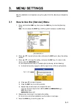
Page 41: ...ting and press the ENT key To return to the menu press the MENU ESC key To enter alphanumeric data for example Ship s Name do the following 1 A character input box appears with the input cursor at the far left position 2 Press or to select character 3 Press the ENT key to confirm selection 4 Repeat step 2 and step 3 to complete the item You can move the input cursor with the ENT and MENU ESC keys ...

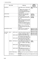
Page 42: ...rom DS 610 IEC61162 1 Ed 2 IEC61162 1 Ed 3 IEC61162 2 Ed 1 IEC61162 1 Ed 4 Input Data Format IEC 61162_IN_1 Select IEC data format input to the channel 1 of the IN port TB2 1 2 in DS 610 main display only IEC61162 1 Ed 2 IEC61162 1 Ed 3 IEC61162 2 Ed 1 IEC61162 1 Ed 4 61162_IN_2 Select IEC data format to input to the channel 2 of the IN port TB2 3 4 in DS 610 main display only 61162_IN_3 Select IE...

Page 43: ...ow Transducer Center Alarm Buzzer Select ON to get the audio alarm when an alarm is violated main display only ON OFF Alarm Hysteresis Set the amount of tolerance to ap ply to the Speed Limit alarm main display only For example if you set 1 kn here and 30 kn for the Speed Limit alarm that alarm is cancelled when ship s speed drops to 29 kn from 30 kn 0 to 5 kn Default 0 kn L L digit Set the number...

Page 44: ...Item Meaning Setting range LOA Ship s length 50 0 to 400 0 m B Ship s width 5 0 to 100 0 m L1 Horizontal distance from the ship s bow to transducer 0 0 m to the setting value for LOA L2 Horizontal distance from port to transducer 0 0 m to the setting value for B L3 Horizontal distance from ship s bow to GPS antenna 0 0 m to the setting value for LOA L4 Horizontal distance from port to GPS an tenna...

Page 45: ...2 5 rise at bow 4 Press to select Heel and press the ENT key 5 Enter the offset value for the heel and press the ENT key setting range 12 5 to 12 5 rise at port 6 Press to select XDCR and press the ENT key 7 Enter the offset value if transducer is not installed perfectly with ship s fore aft line setting range 60 0 to 60 0 Measure the difference between ship s fore aft line and the line on the tra...

Page 46: ...Interference rejection Input Interference can be detected during a noise test and the interference may affect the speed log measurements and readings To reject the interference you can use the in terference rejection circuit inside the transceiver unit The circuit uses the keying pulse KP from the external equipment to reject interfer ence External equipment should be connected to the KP_IN termin...

Page 47: ...hen press the ENT key Note The DS 60 does not have a mode to allow synchronization with external equip ment s KP Interference rejection Output When outputting KP from the DS 60 for the purpose of suppressing interference to other ultrasound equipment remove the TX trigger pulse from the TB4 KP_OUT ter minal 5 V to 15 V DS 610 App 2KΩ H C TB4 KP out App 300Ω Interfering equipment Interference rejec...

Page 48: ...power The Ser vice menu appears 2 Press or to select SIM and press the ENT key 3 Press to select SET TEST Speed and press the ENT key The window for set ting of the test speed appears 4 Press or to select the appropriate spped and press the ENT key 5 Press the PWR key to turn off the power 6 Press the PWR key again to turn on the power The simulation mode starts 7 To stop the simulation mode press...

Page 49: ...er the ground SOG however the DS 60 provides the speed through the water To find the speed through the water a return trip is necessary P1 P1 P2 P2 A B d Sg1 Sg2 Transit posts Transit posts Sg1 d t1 X 3600 kn 1 Sg2 d t2 X 3600 kn 2 Sw St Sg1 kn kn3 Sw St Sg2 kn 4 Adding 4 and 3 we get 2Sw Sg1 Sg2 kn Therefore Sw Sg1 Sg2 2 kn 5 where d distance run nm t1 time taken to run 1 second t2 time taken to ...

Page 50: ...rom A to B measured by DS 60 n2 nm distance run from B or A measured by DS 60 Therefore the average run from A to B measured by DS 60 Therefore the average ship speeds of run 1 and run 2 are calculated as follows Slog1 kn n1 t1 X 3600 Slog2 kn n2 t1 X3600 The average ship speed of round trip is Slog kn Slog1 Slog2 2 6 3 Speed error From 5 and 6 Error Sw Slog Slog X 100 7 This error can be correcte...

Page 51: ...APPENDIX 1 CALIBRATION AP 3 ...

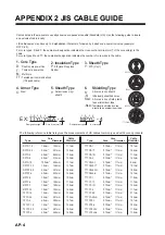
Page 52: ...TTYCY 4 0 75mm2 1 11mm 17 7mm TTYCY 4S 0 75mm2 1 11mm 21 1mm TTYCY 4SLA 0 75mm2 1 11mm 19 5mm TTYCYS 1 0 75mm2 1 11mm 12 1mm TTYCYS 4 0 75mm2 1 11mm 18 5mm TTYCYSLA 1 0 75mm2 1 11mm 11 2mm TTYCYSLA 4 0 75mm2 1 11mm 17 9mm EX TTYCYSLA 4 MPYC 4 Designation type Core Area mm2 Designation type of cores 1 2 3 4 5 6 1 2 3 4 Cables listed in the manual are usually shown as Japanese Industrial Standard JI...

Page 53: ... ߖࠎ ޕ 691 6 2 5 0 1 5 56 14 0 6 6 19 4 241 7 6 5 22 0 2 1 6 722 4 241 7 6 37 6 5 6 5 A 1 1 01 6 2 2 ޓޓ 176 0 ฬ ޓޓ 0 ᢙ 3 6 ㅜ㧛 4 4 5 ภ 01 ဳฬ㧛ⷙᩰ 5 4 26 105 056 6 10 6 4 5 Ꮏ ᢱ 6 5 ⷺ㩘㩨㩣㩎 1 6 575 1 01 ዉ㔚Ꮣ㩍㨺㩖㩩 5 0 6 2 64 1 01 㧔 ߩኸᴺߪ ޔ ෳ ୯ߢߔ ޓޕ 05 105 0 4 9 0 14 4 4 0 10 㧕 㧲㨁㧾㨁㧺㧻 ޓ 㧱㧸㧱㧯㨀㧾㧵㧯 ޓ 㧯㧻 ޓ 㧚㧘㧸㨀㧰 ဳᑼ 㩄㨺㩎㩨 ภ߇㧞Ბߩ႐ว ޔ ਅᲑࠃࠅ Ბߦઍࠊࠆㆊᷰᦼຠߢ ࠅ ޔ߅ߥޓޕߔ ߡߞ ߇߆ࠄߜߤޔ ຠ ߪᄌࠊࠅ ߖࠎ ޕ 691 6 2 5 0 1 5 56 14 0 6 6 19 4 241 7...

Page 54: ...241 7 6 37 6 5 6 5 A 3 1 01 6 2 2 ޓޓ 176 0 ฬ ޓޓ 0 ᢙ 3 6 ㅜ㧛 4 4 5 ภ 01 ဳฬ㧛ⷙᩰ 5 4 26 105 056 6 10 6 4 5 Ꮏ ᢱ 6 5 㩄㩒㩂㩊 ቯ ౕ 6 0 14 100 614 1 01 㩂㩨㩥㩜㨹㩎 41 6 1 01 㩃㨺㩖㩨㩣 ߃ 0 2 6 1 01 㩔㩨㩒㩅㩨㩀㩨㩒 524 0 9 5 4 575 1 01 ⷺⓣઃ㩘㩨㩣㩎 10 1 6 575 1 01 ⷺⓣઃ㩘㩨㩣㩎 10 1 6 575 1 01 ⷺⓣઃ㩘㩨㩣㩎 10 1 6 575 1 01 㩆㨺㩣㩦㨹㩆㨶㨺 5 9 5 4 575 9 1 01 㨾㩁㩆㩨㨸㨽㩀㩨㩇㩃㨹㩎 37 5 65 6 1 01 㩆㩢㩄㩧㩂㩨㩢㩇 4 5 1 01 㧔 ߩኸᴺߪ ޔ ෳ ୯ߢߔ ޓޕ 05 105 0 4 9 0 14 4 4 0 10 㧕 㧲㨁...

Page 55: ...5 6 5 A 5 1 01 6 2 2 ޓޓ 176 0 ฬ ޓޓ 0 ᢙ 3 6 ㅜ㧛 4 4 5 ภ 01 ဳฬ㧛ⷙᩰ 5 4 26 105 056 6 10 6 4 5 Ꮏ ᢱ 6 5 㒐 ᐳ 9 6 42411 9 5 4 1 01 㒐 㩔㩩㨹㩁㩧 9 6 42411 5 6 1 01 㩂㩨㩡㩧㩎㩨 ઃ 0 0 22 5 㩠㨽 1 01 ⷺ㩏㨹㩎 㩆㨷 10 076 575 1 01 ᐔᐳ 6 9 5 4 575 1 01 㩔㩨㩒ᐳ 524 0 9 5 4 575 1 01 ⷺ㩏㨹㩎 㩆㨷 10 076 575 1 01 㩔㩨㩒ᐳ 524 0 9 5 4 575 1 01 ⷺ㩘㩨㩣㩎 10 1 6 575 1 01 㩄㩇㩝㩂㩨㩢㩇㩊㩨㨼㩏㩙㨹㩂㩇 4 5 0Q 㩆㩨㨶㩔㩨㩡㩋㨷㨺㩖㩨 1 01 㧔 ߩኸᴺߪ ޔ ෳ ୯ߢߔ ޓޕ 05 105 0 4 9 0 14 4 4 0 1...

Page 56: ...ࠅ ޔ߅ߥޓޕߔ ߡߞ ߇߆ࠄߜߤޔ ຠ ߪᄌࠊࠅ ߖࠎ ޕ 691 6 2 5 0 1 5 56 14 0 6 6 19 4 241 7 6 5 22 0 2 1 6 722 4 241 7 6 37 6 5 6 5 A 7 1 01 6 2 2 ޓޓ 176 0 ฬ ޓޓ 0 ᢙ 3 6 ㅜ㧛 4 4 5 ภ 01 ဳฬ㧛ⷙᩰ 5 4 26 105 056 6 10 6 4 5 Ꮏ ᢱ 6 5 㩀㩨㩇㩃㨹㩎 5 6 1 01 㧔 ߩኸᴺߪ ޔ ෳ ୯ߢߔ ޓޕ 05 105 0 4 9 0 14 4 4 0 10 㧕 㧲㨁㧾㨁㧺㧻 ޓ 㧱㧸㧱㧯㨀㧾㧵㧯 ޓ 㧯㧻 ޓ 㧚㧘㧸㨀㧰 ဳᑼ 㩄㨺㩎㩨 ภ߇㧞Ბߩ႐ว ޔ ਅᲑࠃࠅ Ბߦઍࠊࠆㆊᷰᦼຠߢ ࠅ ޔ߅ߥޓޕߔ ߡߞ ߇߆ࠄߜߤޔ ຠ ߪᄌࠊࠅ ߖࠎ ޕ 691 6 2 5 0 1 5 56 14 0 6 6 19 4 241 7 6...

Page 57: ...ߞ ߇߆ࠄߜߤޔ ຠ ߪ ᄌࠊࠅ ߖࠎ ޕ 691 6 2 5 0 1 5 56 14 0 6 6 19 4 241 7 6 5 22 0 2 1 6 722 4 241 7 6 37 6 5 6 5 4 A 9 1 01 6 2 52 6 01 0 1 2 46 176 0 9 01 14 2 4 5 6 2 4 8 5 52 4 914 0 37 06 6 4 4 5 1 01 1 01 2 5 2 01 52 4 2 465 56 14 7 5 5 65 2 4 8 55 6 2 01 6 5 㩕㨷㨺㩇㩨 1 8 2 55 67 75 4 5 0 74701 64 1 6 9 01 㧔 ߩኸᴺߪ ޔ ෳ ୯ߢߔ ޓޕ 05 105 0 4 9 0 ޓ 14 4 4 0 10 㧕 2 ဳᑼ 㩄㨺㩎㩨 ภ߇㧞Ბߩ႐ว ޔ ਅᲑࠃࠅ Ბߦઍࠊࠆㆊᷰᦼຠߢ ࠅ ޔ߅ߥޓޕߔ ߡߞ ߇߆ࠄߜߤ...

Page 58: ...ߥޓޕߔ ߡߞ ߇߆ࠄߜߤޔ ຠ ߪᄌࠊࠅ ߖࠎ ޕ 691 6 2 5 0 1 5 56 14 0 6 6 19 4 241 7 6 5 22 0 2 1 6 722 4 241 7 6 37 6 5 6 5 A 11 1 01 6 2 2 ޓޓ 176 0 ฬ ޓޓ 0 ᢙ 3 6 ㅜ㧛 4 4 5 ภ 01 ဳฬ㧛ⷙᩰ 5 4 26 105 5514 5 ઃዻຠ 6 5 5 5 5 8 㩖㨲㩣㩊㨺㩂㩢㨺㩏㨺 0 0 16 1 01 㩒㩆㩨㩁㨶㨹㩖㩩 2 1 01 4 㩖㩊 ຠ 4 55 2 1 01 㧔 ߩኸᴺߪ ޔ ෳ ୯ߢߔ ޓޕ 05 105 0 4 9 0 14 4 4 0 10 㧕 㧲㨁㧾㨁㧺㧻 ޓ 㧱㧸㧱㧯㨀㧾㧵㧯 ޓ 㧯㧻 ޓ 㧚㧘㧸㨀㧰 ဳᑼ 㩄㨺㩎㩨 ภ߇㧞Ბߩ႐ว ޔ ਅᲑࠃࠅ Ბߦઍࠊࠆㆊᷰᦼຠߢ ࠅ ޔ߅ߥޓޕߔ ߡߞ ߇߆ࠄߜߤޔ ຠ ߪᄌࠊࠅ ߖࠎ ޕ 6...

Page 59: ...8 Mar 2010 Y NISHIYAMA D 1 ...

Page 60: ...18 Dec 2012 Y NISHIYAMA D 2 ...

Page 61: ...18 Dec 2012 Y NISHIYAMA D 3 ...

Page 62: ...D 4 30 Jun 2015 H MAKI ...

Page 63: ...D 5 30 Jun 2015 H MAKI ...

Page 64: ...1 Jul 2011 Y NISHIYAMA D 6 ...

Page 65: ...29 Mar 2011 Y NISHIYAMA D 7 ...

Page 66: ...29 Mar 2011 Y NISHIYAMA D 8 ...

Page 67: ...D 9 30 Jun 2015 H MAKI ...

Page 68: ...D 10 30 Jun 2015 H MAKI ...

Page 69: ...D 11 15 Apr 2016 H MAKI ...

Page 70: ...D 12 15 Apr 2016 H MAKI ...

Page 71: ...D 13 15 Apr 2016 H MAKI ...

Page 72: ...D 14 15 May 2015 H MAKI ...

Page 73: ...1 24VDC5_N 24VDC5_P DST2DSP5_N DST2DSP5_P 24VDC4_N 24VDC4_P DST2DSP4_N DST2DSP4_P 24VDC3_N 24VDC3_P DST2DSP3_N DST2DSP3_P RD2A RD2B DC_H DC_C 1 2 TTYC Y S 1 TTYC Y S 4 MAX 100m P P 1 9 10 11 12 NC TB3 1 2 3 4 5 6 7 8 1 P P P P P 1 2 3 4 5 6 7 8 9 10 TB9 12 NC NC 11 NC 13 15 NC 14 ANA_DISP1_H ANA_DISP1_C ANA_RNG1_P ANA_RNG1_N ANA_DISP2_P ANA_DISP2_N ANA_RNG2_P ANA_RNG2_N ANA_V_P ANA_V_N ANA_C_P ANA...

Page 74: ...8 TRX2DST_P TRX2DST_N DST2TRX_P DST2TRX_N TRX_KP_P TRX_KP_N 1 2 3 4 5 6 7 NC NC 8 TRX2DST_P TRX2DST_N DST2TRX_P DST2TRX_N TRX_KP_P TRX_KP_N TB2 TB1 5 6 3 4 1 2 TRX_KP_N TRX_KP_P TB2 TRX2DST_N TRX2DST_P DST2TRX_N DST2TRX_P NC 7 P P P 1 TTYCY 4S DS 645B JUNCTION BOX 接続箱 DS 620 送受信部 TRANSCEIVER TTYCY 19S 10S 1 P P P 7 TB3 1 2 3 4 5 6 TB3 NC 160V E NC 0V 0V NC 120V 0V 120V DPYCY 4 1 1 2 TB102 AC_OUT_C...

Reviews:

Related manuals for DS-60