1. INSTALLATION
1-4
1.2
Transceiver Unit DS-620
Installation considerations
• Since the transceiver unit generates heat, install it in a dry, well-ventilated place.
The cooling fans at the top of the unit must not be obstructed, to allow heat to es-
cape.
• This unit is designed for bulkhead mounting to permit dissipation of heat. If bulkhead
mounting is absolutely impossible, mount the unit on the floor leaving at least 350
mm clearance between it and the floor to permit dissipation of heat.
• Reinforce the mounting area, if necessary.
• Leave space around the unit for maintenance and checking. Refer to the drawing at
the back of this manual for minimum recommended maintenance space.
• A magnetic compass will be affected if the transceiver unit is placed too close to it.
Observe the compass safe distances to prevent disturbance to the magnetic com-
pass (page i).
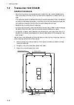
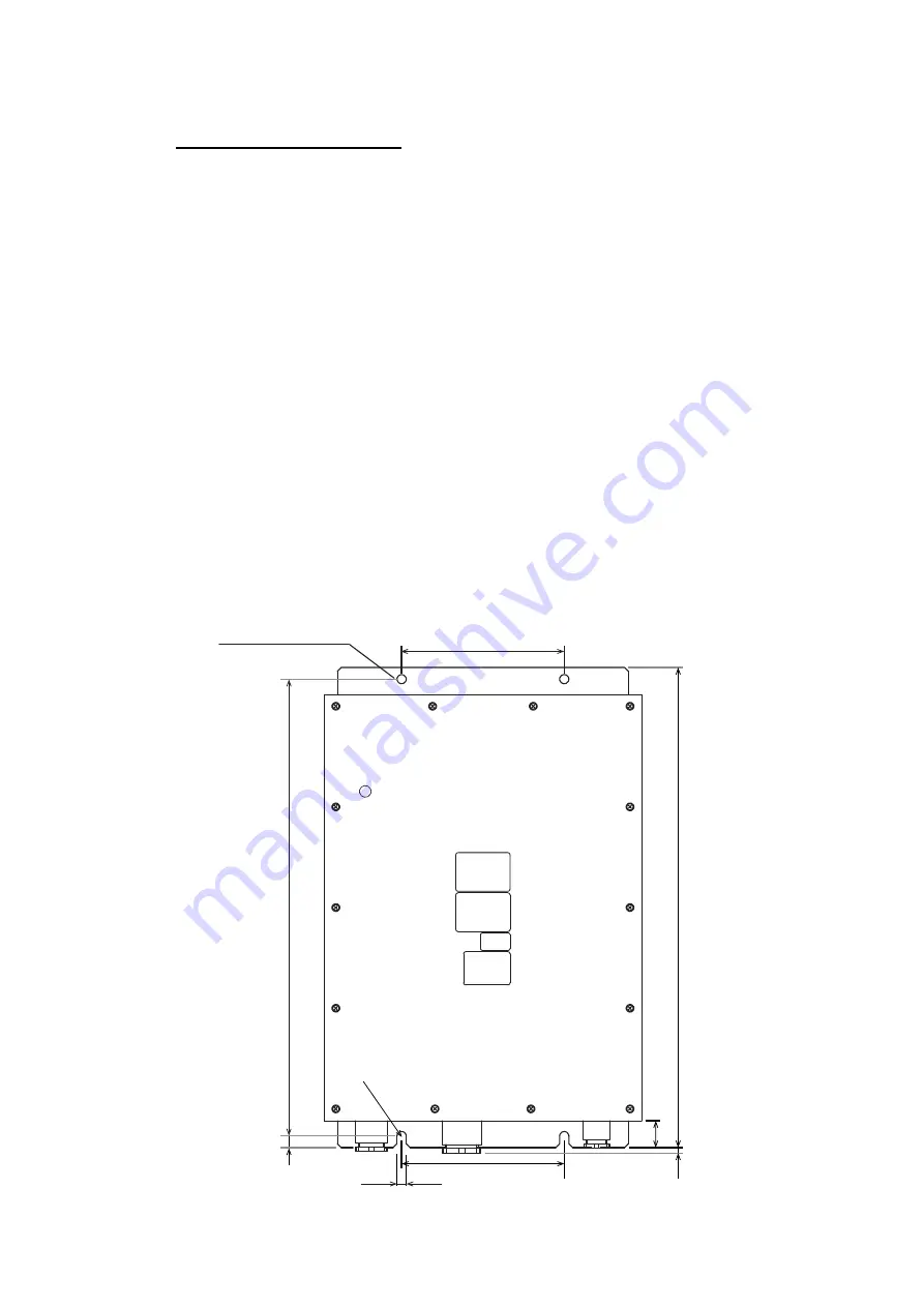
Use four hex. bolts (M10x20) to fix the transceiver unit to the mounting area. See the
outline drawing at the back of this manual.
1. Screw in lower hex. bolts so there is 5 mm clearance between bottom of screw
head and bulkhead.
2. Hang the unit on the bolts, then tighten the bolts.
3. Fasten the unit with upper hex. bolts.
210±1 (8.27”)
Fixing hole 2-ø12
15 (0.59”)
590±1 (23.23”)
620 (24.41”)
35 (1.38”)
(7)
210±1 (8.27”)
12 (0.47”)
2-R6
Summary of Contents for DS-60
Page 51: ...APPENDIX 1 CALIBRATION AP 3 ...
Page 59: ...8 Mar 2010 Y NISHIYAMA D 1 ...
Page 60: ...18 Dec 2012 Y NISHIYAMA D 2 ...
Page 61: ...18 Dec 2012 Y NISHIYAMA D 3 ...
Page 62: ...D 4 30 Jun 2015 H MAKI ...
Page 63: ...D 5 30 Jun 2015 H MAKI ...
Page 64: ...1 Jul 2011 Y NISHIYAMA D 6 ...
Page 65: ...29 Mar 2011 Y NISHIYAMA D 7 ...
Page 66: ...29 Mar 2011 Y NISHIYAMA D 8 ...
Page 67: ...D 9 30 Jun 2015 H MAKI ...
Page 68: ...D 10 30 Jun 2015 H MAKI ...
Page 69: ...D 11 15 Apr 2016 H MAKI ...
Page 70: ...D 12 15 Apr 2016 H MAKI ...
Page 71: ...D 13 15 Apr 2016 H MAKI ...
Page 72: ...D 14 15 May 2015 H MAKI ...


