background image

$

%

&

'5

$:1

&+

(&.(

'

$3

3529

('

':

*1R

7,7/

(

1$0(

ྡ⛠

5(

)1R

6&

$/(

0$66

NJ

7

<$0$6$.

,

,17

(5

&21

1(

&7,

21

',

$*

5$0

┦஫⤖⥺

࣮ࢲ࣮ࢭࣥࢧ

5$

'$

5

6

(1

6

25

+

0$.,

ὀグ

127(

㸨㸯

㸧㐀⯪ᡤ

ᡭ㓄ࠋ

㸨㸰

㸧࢜ࣉࢩ

ࣙࣥࠋ

6+,3<$5'

6833/<

237,21

5-

/$1

࢖࣮ࢧ

ࢿࢵࢺࣁ

5-

+8%

(7+(51(

7

+8%

08/7,

)8

1&7,21

',63/$<

࣐ࣝࢳࣇ

࢓ࣥࢡ

ࢩࣙࣥ

ࢹ࢕ࢫࣉ

ࣞ࢖

25

ࡲࡓࡣ

-81&7,21

%2;

7/&$7

ࢪࣙ࢖ࣥࢺ࣎ࢵ

ࢡࢫ

7=7

%%

7=7/)

)

&

&

%

$XJ

$XJ

-

࢔࢝

࢔࢜

5('

%/8

)

5836))0P

ȭ

9'&

)

5836))00

0P

୰⥺㒊

$1

7(11$

81

,7

56

%

P

$'56

$

;&ODVV

,9VT

$'5

6$$

;&ODVV

'56

$

$

$

;

&OD

VV

9

'&

㺚㺹

㺖㺹

:+7

%/.

9+30996

[&

P

08/7,

)81&7,21

',63/$<

࣐ࣝࢳ

ࣇ࢓ࣥࢡ

ࢩࣙࣥࢹ

࢕ࢫࣉ

ࣞ࢖

ࢿࢵࢺ

࣮࣡ࢡᶵ

1(7:25.

(48,30

(17

7=7

%%7=7

/))

02'=P

673

&$%/(

3/Aug/2016 H.MAKI

S-1

Summary of Contents for DRS12AX X-Class

Page 1: ...erations 1 1 2 Included Items 3 1 3 Required Tools and Materials 4 1 4 Fastening the Radiator to the Radiator Bracket 5 1 5 Mounting the Antenna Unit 7 1 6 Wiring 10 2 INITIAL SETUP 15 2 1 Initial Setup for TZT9 TZT14 TZTBB 16 2 2 Initial Setup for TZTL12F TZTL15F 18 3 MAINTENANCE TROUBLE SHOOTING 23 3 1 Maintenance 24 3 2 Troubleshooting 25 3 3 Replacement of Fuse 25 3 4 Life of Parts 26 APPENDIX...

Page 2: ......

Page 3: ...quipment Connection of an incorrect power supply can cause fire or damage the equipment Use only the specified power and signal cable Fire or damage to the equipment can result if a different cable is used Wear a safety belt and hard hat when working on the antenna unit Serious injury or death can result if someone falls from the radar mast Do not disassemble or modify the equipment Fire electrica...

Page 4: ... electromagnetic radio frequency RF energy which can be harmful particularly to your eyes Never look directly into the antenna aperture from a close distance while the radar is in operation or expose yourself to the transmitting antenna at a close distance Distances at which RF radiation levels of 100 50 and 10 W m2 exist are given in the table below WARNING 0 1 m XN10A 3 m 0 5 m 100 W m2 50 W m2 ...

Page 5: ...or later DRS12A X Class and DRS25A X Class TZT9 TZT14 and TZTBB Version 5 01 or later Planned release End of 2016 TZTL12F and TZTL15F Version 4 01 or later Planned release End of 2016 Standard supply Optional or local supply Antenna Unit RSB 134 Multi Function Display NavNet TZtouch Navnet TZtouch 2 Multi Function Display NavNet TZtouch Navnet TZtouch 2 Ethernet HUB HUB 101 Ship s battery 24 VDC C...

Page 6: ...e assembly 30 m supplied for DRS6A X Class CP03 37400 000 033 082 Cable assembly 10 m and fuse 10 A for re placement supplied for DRS12A 25A X Class CP03 37410 000 033 083 Cable assembly 15 m and fuse 10 A for re placement supplied for DRS12A 25A X Class CP03 37420 000 033 084 Cable assembly 20 m and fuse 10 A for re placement supplied for DRS12A 25A X Class CP03 37430 000 033 085 Cable assembly 3...

Page 7: ...am width of the radiator will cause only a small shadow sector However a horizontal spreader or cross trees in the same horizontal plane as the antenna unit would be a much more serious obstruction You would need to place the antenna unit well above or below it Be sure there are no metallic objects near the antenna It is rarely possible to place the antenna unit where a completely clear view in al...

Page 8: ...lation location A magnetic compass will be affected if the antenna unit is too close to the compass Observe the compass safe distances mentioned in the SAFETY INSTRUCTIONS to prevent interference to a magnetic compass To ensure proper emission of radar waves do not paint the radiator Referring to the outline drawings at the back of this manual allow space for main tenance and service When this ant...

Page 9: ...4 pcs Flat washer M12 4 pcs Spring washer M12 4 pcs Hex nut M12 8 pcs Insulation sheet 4 pcs Spare fuse 1 pcs DRS6A X Class 5 A DRS12A 25A X Class 10 A Documents 1 set Cable assembly Cable assembly 1 1 pcs 10 m 15 m 20 m or 30 m 1 Select the appropriate length when purchasing 2 Selectable for DRS6A X Class only Supplied for DRS12A X Class and DRS25A X Class 㻔㻝㻜㻌㻭㻕 10A Fuse for replacement 1 pcs La...

Page 10: ...o Name Remarks 1 Electrical drill For making the mounting holes drill bit I 15 mm 2 Phillips head screw driver 3 for securing the cable cover 3 Wrench For M8 Hex size 13 mm and M12 Hex size 19 mm 4 Hex L wrench For fastening the stud bolts Hex size 6 mm 5 Self vulcanizing tape For waterproofing the junction of connectors 6 Vinyl tape 7 Cable tie For securing the cables 8 Ground wire IV 2sq 1 2 3 5...

Page 11: ... Remove the radiator cap from the radiator bracket 2 Apply adhesive to the surface of the radiator bracket as shown in the figure below 3 Set the O ring to the radiator bracket Radiator bracket Radiator cap Adhesive Top view Scanner unit 10 mm 10 mm Adhesive application area O ring ...

Page 12: ...x bolt M8u30 then apply adhesive 6 Fasten the radiator to the radiator bracket using four bolt assemblies prepared at step 5 Note Be sure to align the waveguide location between the radiator and radiator bracket before fastening bolt assemblies Bottom view Radiator Adhesive Flat washer Spring washer Hex bolt Adhesive Hex bolt 4 pcs Align the waveguide location Detailed view after securing the radi...

Page 13: ...ud bolts must make contact with the bottom of the threaded holes Note Do NOT cover the vent hole at the bottom of the unit Apply adhesive to these bolts and holes Radiator Bolt assembly side view detailed Apply adhesive to the junction between the radiator and radiator bracket Apply adhesive to the junction between the radiator and radiator bracket Flat washer Spring washer Hex bolt Adhesive Radia...

Page 14: ...le Adhesive Stud bolt Do not fasten stud bolts tightly after the bolts contact with the bottom of the threaded holes If the bolts are fastened excessively the chassis bottom may be damaged which can result in malfunction The projected bolt length after the bolts contact with the bottom of the threaded holes is approx 50 mm This data is for reference purpose only NOTICE Adhesive Stud bolt Insulatio...

Page 15: ...r may get damaged Hoist the antenna unit slowly If the antenna unit is hoisted too quickly the bracket can be damaged 7 Place the antenna unit on the mounting platform with the BOW mark on the unit aligned with the ship s bow 8 Secure the antenna unit using the supplied flat washers M12 4 pcs spring washers M12 4 pcs and hex nuts M12 8 pcs Belt sling 2 pcs OK Belt slings are set to the radiator br...

Page 16: ...rating label to the fuse holder For details see How to Re place the Fuse C32 01604 The cable assembly and power LAN cables have connector s Do NOT cut the ca ble assembly and power LAN cables even if the cables are run through a radar mast When you replace the DRS4A 6A 12A 25A with the DRS6A X Class DRS12A X Class DRS25A X Class the existing cable cannot be used Use only the cable as sembly suppli...

Page 17: ...l supply and ground wire from the antenna unit using the terminal screw M4x10 that is pre attached to the cable cover Cable cover Cable cover Self vulcanizing tape 1 Wrap the junction of the connectors with one layer of self vulcanizing tape 2 Change wrap direction and wrap one layer of the self vulcanizing tape again Self vulcanizing tape 3 Wrap one layer of the vinyl tape over the self vulcanizi...

Page 18: ...d LAN Adhesive Ex 1 Ex 2 Adhesive Adhesive Hex bolt Flat washer Flat washer Spring washer Hex nut Ground wire Ground wire Hex nut Spring washer Flat washer Hex nut Weld here Fix the cable to this cable clamp using a cable tie Fix the cable to this cable clamp using a cable tie Ground wire from the ship s ground Ground wire from the ship s ground Cable assembly Cable assembly Power LAN cable Power ...

Page 19: ...rminal Black wire The black wire is a shielding wire for grounding Note 1 The antenna unit has no power switch Connect the antenna unit to a dis tribution switchboard with a switch for power control Note 2 If the voltage of the ship s battery is 12 VDC prepare a DC to DC con verter whose output current is 10 A or more Note 3 The antenna unit cannot accept input voltage of more than 24 VDC Cable as...

Page 20: ...1 INSTALLATION AND WIRING 14 ...

Page 21: ... sure no one is near the antenna Prevent the potential risk of being struck by the rotating antenna which can result in serious injury or death WARNING The radar antenna emits electromagnetic radio frequency RF energy which can be harmful particularly to your eyes Never look directly into the antenna aperture from a close distance while the radar is in operation or expose yourself to the transmitt...

Page 22: ...p 6 Set the items referring to the table shown below Menu Radar Radar Initial Setup Menu item Description Antenna Rotation Select the antenna rotation speed Antenna Heading Align See How to align the antenna heading on page 17 Main Bang Suppression If main bang appears at the screen center slide the circle icon while watching the radar echo on the left side of the display until the main bang disap...

Page 23: ...ce Manual Tuning Manually tune the radar Not available when Auto Tuning is enabled Radar Monitoring Display various information regarding the connected ra dar Radar Optimization Automatically adjust magnetron output and tuning for the connected radar Note Be sure to perform Radar Optimization after re placing the magnetron ARPA Advanced Settings Do not change these settings Menu item Description O...

Page 24: ...e 5 Confirm that the target echo is displayed at correct bearing on the screen 2 2 Initial Setup for TZTL12F TZTL15F 1 Tap the Home icon to show the home screen and display mode settings 2 Tap Radar from the Settings menu 3 Tap Radar Source then select the appropriate antenna unit Note If the antenna unit is connected but does not appear in the Radar Source list close the list and open it again Th...

Page 25: ... figure on the right enter the radar antenna positioning bow stern Longitudinal and port starboard Lateral position from the origin Lateral Port Antenna Height Select the height of the antenna above the waterline Auto Tuning Enable disable auto tuning for the connected radar Tuning Source For dual range display select the range to use as the manual tuning source Manual Tuning Manually tune the rad...

Page 26: ... be shown or hidden with Show Scale Slider in the Settings Radar menu 000 010 020 030 040 050 060 070 080 090 100 110 120 130 140 150 160 170 180 190 200 210 220 230 240 250 260 270 280 290 300 310 320 330 340 350 000 010 020 030 040 050 060 070 080 090 100 110 120 130 140 150 160 170 180 190 200 210 220 230 240 250 260 270 280 290 300 310 320 330 340 350 Correct bearing relative to heading a Appa...

Page 27: ...Radar menu 5 Drag the Radar menu to show the RADAR INITIAL SETUP menu 6 Tap Antenna Heading Align 7 Key in the offset value so that the target is displayed at the very top of the screen setting range 179 9 to 180 clockwise direction counterclockwise direc tion then tap the icon 8 Confirm that the target echo is displayed at correct bearing on the screen ...

Page 28: ...2 INITIAL SETUP 22 This page is intentionally left blank ...

Page 29: ...int anti corrosive sealant or contact spray to coating or plastic parts of the equipment Those items contain organic solvents that can damage coating and plastic parts especially plastic connectors WARNING NOTICE Do not open the equipment Hazardous voltage which can cause electrical shock exists inside the equipment Only qualified personnel should work inside the equipment Turn off the antenna uni...

Page 30: ... on the radiator cause signal attenu ation resulting in loss of sensitiv ity Wipe radiator with a freshwater moistened cloth The radiator is made of AES Acry lonitrile Ethylene Styrene resin Therefore do not used gasoline benzene and the like to clean the ra diator If the radiator is iced use a wooden or plastic headed hammer to re move the ice DO NOT use a steel hammer Ground con nection Check fo...

Page 31: ...ure is not updated or the picture freezes Check that all cables are tightly fastened Check the cables for damage If the picture has frozen reboot the multi function display You tuned the receiver or in creased the gain but radar echoes are too week The magnetron may required replacement Contact your dealer You changed the range but the radar picture does not change Try to change the range again Re...

Page 32: ...n antenna motor reaches the end of its life the antenna s rotation may stop or abnormal noise sounds from the antenna unit If such symptom occurs contact your dealer about replacement of the antenna motor Name Type Code No Approx Life Remarks Magnetron MAF1422B 000 158 788 12 5 000 hours For DRS6A X Class FNE1201 001 245 890 5 000 hours For DRS12A X Class MG5436 000 140 762 13 5 000 hours For DRS2...

Page 33: ...N 2 1 Tx frequency 9410 30 MHz 2 2 Output power DRS6A X Class 6 kW nominal DRS12A X Class 12 kW nominal DRS25A X Class 25 kW nominal 2 3 Duplexer Ferrite circulator with diode limiter 2 4 Intermediate frequency 60 MHz 2 5 Range Pulse length and Pulse Repetition Rate PRR Range NM Pulse length μs PRR Hz approx 0 125 to 0 75 0 08 3000 1 to 1 5 0 15 1500 2 0 3 1000 3 to 4 0 5 600 6 to 8 0 8 600 12 to ...

Page 34: ...ss 24 VDC 4 0 A DRS12A X Class 24 VDC 4 5 A DRS25A X Class 24 VDC 5 6 A 5 ENVIRONMENTAL CONDITIONS 5 1 Ambient temperature 25 C to 55 C storage 30 C to 70 C 5 2 Relative humidity 95 or less at 40 C 5 3 Degree of protection IP56 5 4 Vibration IEC 60945 Ed 4 6 UNIT COLOR N9 5 ...

Page 35: ...s aux appareils radio exempts de licence L exploitation est autorisée aux deux conditions suivantes 1 l appareil ne doit pas produire de brouillage et 2 l utilisateur de l appareil doit accepter tout brouillage radioélectrique subi même si le brouillage est susceptible d en compromettre le fonctionnement Caution Exposure to Radio Frequency Radiation This equipment complies with IC radiation exposu...

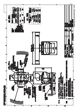
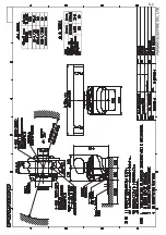
Page 36: ...80 17 ᆺ 7 03 7 㺺 㺒㺐 ഛせ㡿 167 7 21 0 18 0 䠄 ᅗ䛾ᑍἲ䛿䚸ཧ 䛷䛩䚹㻌㻌㻰㻵㻹㻱㻺㻿㻵㻻㻺㻿㻌㻵㻺㻌㻰㻾㻭㼃㻵㻺㻳㻌㻲㻻㻾㻌㻾㻱㻲㻱㻾㻱㻺㻯㻱㻌㻻㻺㻸㼅㻚䠅 A 1 㹎㸿㹁㹉㹇㹌㹅ࠉ㹊㹇㹑㹒 56 1 0 2 8 7 1 6 5 37 21 2 θ 4 7 ࣘࢽࢵࢺ 81 7 ᮏయ㒊 6 11 5 81 7 56 ணഛရ 63 5 3 576 ணഛရ 63 5 3 576 63 ᕤ ᮦᩱ 167 7 21 0 7 5 6 ᕤ ᮦᩱ 167 7 21 0 7 5 6 3 ᅗ 2 80 17 ᆺ 7 03 7 㺺 㺒㺐 ഛせ㡿 167 7 21 0 18 0 䠄 ᅗ䛾ᑍἲ䛿䚸ཧ 䛷䛩䚹㻌㻌㻰㻵㻹㻱㻺㻿㻵㻻㻺㻿㻌㻵㻺㻌㻰㻾㻭㼃㻵㻺㻳㻌㻲㻻㻾㻌㻾㻱㻲㻱㻾㻱㻺㻯㻱㻌㻻㻺㻸㼅㻚䠅 A 2 ...

Page 37: ...0 0 0 0 0 0 0 0 1 7 6 0 5 4 26 10 1 ͳ 3 6 70 6 㨻㩧㩍㩏 06 00 0 㨻㩧㩍㩏Ꮏ 06 00 056 6 10 6 4 5 Ꮏ ᢱ 056 6 10 6 4 5 2 䍘㪄䍢䍼 ภᧃየ䈱㪲㪁㪁㪴䈲䇮ㆬᛯຠ䈱ઍ 䍘䍎䍢䍼䉕 䈚䉁䈜䇯 㪚㪦㪛㪜㩷㪥㪬㪤㪙㪜㪩㩷㪜㪥㪛㪠㪥㪞㩷㪮㪠㪫㪟㩷㩹㪁㪁㩹㩷㪠㪥㪛㪠㪚㪘㪫㪜㪪㩷㪫㪟㪜㩷㪚㪦㪛㪜㩷㪥㪬㪤㪙㪜㪩㩷㪦㪝㩷㪩㪜㪧㪩㪜㪪㪜㪥㪫㪘㪫㪠㪭㪜㩷㪤㪘㪫㪜㪩㪠㪘㪣㪅 䋨 䈱ኸᴺ䈲䇮ෳ ୯䈪䈜䇯㩷㩷㪛㪠㪤㪜㪥㪪㪠㪦㪥㪪㩷㪠㪥㩷㪛㪩㪘㪮㪠㪥㪞㩷㪝㪦㪩㩷㪩㪜㪝㪜㪩㪜㪥㪚㪜㩷㪦㪥㪣㪰㪅䋩 ဳᑼ㪆䍘䍎䍢䍼 ภ䈏䋲Ბ䈱႐ว䇮ਅᲑ䉋䉍 Ბ䈮ઍ䉒䉎ㆊᷰᦼຠ䈪䈅䉍䇮䈬䈤䉌䈎䈏 䈦䈩䈇䉁䈜䇯䇭䈭䈍䇮ຠ 䈲ᄌ䉒䉍䉁䈞䉖䇯 㪫㪮㪦㩷㪫㪰㪧㪜㪪㩷㪘㪥㪛㩷㪚㪦㪛㪜㪪㩷㪤㪘㪰㩷㪙㪜㩷㪣㪠㪪㪫㪜㪛㩷㪝㪦㪩㩷㪘㪥㩷㪠㪫㪜㪤㪅㩷㩷㪫㪟㪜㩷㪣㪦㪮㪜㪩㩷...

Page 38: ... 62 7 6 7 6 5 0 686 2 12 㸦 ᅗࡢᑍἲࡣࠊཧ ࡍࠋࠉ 0 16 216 1 5 1 25 5 5 1 21 㸧 㹄㹓㹐㹓㹌㹍ࠉ㹃㹊㹃㹁㹒㹐㹇㹁ࠉ㹁㹍ࠉ㸬㸪㹊㹒㹂 0 A 5 2 12 7 3 3 ࠉࠉᅗ 287 1 ྡࠉࠉ 1 0 ᩘ㔞 4 7 㸭ഛ 5 0 5 6 ྕ 12 ᆺྡ㸭つ᱁ 6 5 37 216 167 7 21 0 7 5 6 ᕤ ᮦᩱ ࣂࢿᗙ㔠 635 1 6 5 0 686 2 12 㺮㺔㺼㺕 ᖹᗙ㔠 7 6 5 0 686 2 12 භゅ㺛㺶㺺㺶 㺬㺼㺷㺢 21 6 27 2 7 0 686 2 12 2㺶㺻㺖㺼 6 2 5 1 6 25 1 5 1 2 12 㺗㺮㺚㺎㺷 6 21 58 5 6 㺏㺷㺮㺟㺋㺎㺪㺼 2 12 㸦 ᅗࡢᑍἲࡣࠊཧ ࡍࠋࠉ 0 16 216 1 5 1 25 5 5 1 21 㸧 㹄㹓㹐㹓㹌㹍ࠉ㹃㹊㹃㹁㹒㹐㹇㹁ࠉ㹁㹍...

Page 39: ...7 2 12 㺗㺎㺪㺼㺷 ရ 66 0 58 3 6 0 㑅ᢥࠉ72 6 7 2 12 㺗㺎㺪㺼㺷 ရ 66 0 58 3 6 0 㑅ᢥࠉ72 6 7 2 12 㸦 ᅗࡢᑍἲࡣࠊཧ ࡍࠋࠉ 0 16 216 1 5 1 25 5 5 1 21 㸧 㹄㹓㹐㹓㹌㹍ࠉ㹃㹊㹃㹁㹒㹐㹇㹁ࠉ㹁㹍ࠉ㸬㸪㹊㹒㹂 0 A 7 㹎㸿㹁㹉㹇㹌㹅ࠉ㹊㹇㹑㹒 3 0 1 0 2 8 7 1 6 5 37 21 2 θ 4 7 ᕤ ᮦᩱ 167 7 21 0 7 5 6 㺗㺎㺪㺼㺷 㺖㺮㺩㺻 66 0 58 3 6 0 㺩㺋㺎㺛㺼 86 79 9 㺩㺋㺎㺛㺼㺨㺶㺭㺎㺖 86 㺩㺋㺎㺛㺼 せ㡿 2 72 5 3 7 86 䠄 ᅗ䛾ᑍἲ䛿䚸ཧ 䛷䛩䚹㻌㻌㻰㻵㻹㻱㻺㻿㻵㻻㻺㻿㻌㻵㻺㻌㻰㻾㻭㼃㻵㻺㻳㻌㻲㻻㻾㻌㻾㻱㻲㻱㻾㻱㻺㻯㻱㻌㻻㻺㻸㼅㻚䠅 A 8 ...

Page 40: ...9 㺩㺋㺎㺛㺼㺨㺶㺭㺎㺖 86 㺩㺋㺎㺛㺼 せ㡿 2 72 5 3 7 86 䠄 ᅗ䛾ᑍἲ䛿䚸ཧ 䛷䛩䚹㻌㻌㻰㻵㻹㻱㻺㻿㻵㻻㻺㻿㻌㻵㻺㻌㻰㻾㻭㼃㻵㻺㻳㻌㻲㻻㻾㻌㻾㻱㻲㻱㻾㻱㻺㻯㻱㻌㻻㻺㻸㼅㻚䠅 A 9 㹎㸿㹁㹉㹇㹌㹅ࠉ㹊㹇㹑㹒 3 0 1 0 2 8 7 1 6 5 37 21 2 θ 4 7 ᕤ ᮦᩱ 167 7 21 0 7 5 6 㺗㺎㺪㺼㺷 㺖㺮㺩㺻 66 0 58 3 6 0 㺩㺋㺎㺛㺼 86 79 9 㺩㺋㺎㺛㺼㺨㺶㺭㺎㺖 86 㺩㺋㺎㺛㺼 せ㡿 2 72 5 3 7 86 䠄 ᅗ䛾ᑍἲ䛿䚸ཧ 䛷䛩䚹㻌㻌㻰㻵㻹㻱㻺㻿㻵㻻㻺㻿㻌㻵㻺㻌㻰㻾㻭㼃㻵㻺㻳㻌㻲㻻㻾㻌㻾㻱㻲㻱㻾㻱㻺㻯㻱㻌㻻㻺㻸㼅㻚䠅 A 10 ...

Page 41: ...せ㡿 2 72 5 3 7 86 䠄 ᅗ䛾ᑍἲ䛿䚸ཧ 䛷䛩䚹㻌㻌㻰㻵㻹㻱㻺㻿㻵㻻㻺㻿㻌㻵㻺㻌㻰㻾㻭㼃㻵㻺㻳㻌㻲㻻㻾㻌㻾㻱㻲㻱㻾㻱㻺㻯㻱㻌㻻㻺㻸㼅㻚䠅 A 11 2 12 7 3 63 7 0 12 1 0 2 3 3 57 287 1 12 25 3 5 6 6 7 3 5 9 9 6 63 5 25 1 48 17 7 5 0 5 6 2 12 2 12 3 6 3 12 63 5 3 576 67 25 8 6 6 76 3 5 9 9 66 7 3 12 5 㺩㺋㺎㺛㺼 58 3 6 8 86 0 5 6 1 0 85812 75 2 7 12 㸦 ᅗࡢᑍἲࡣࠊཧ ࡍࠋࠉ 0 16 216 1 5 1 ࠉ 25 5 5 1 21 㸧 3 A 12 ...

Page 42: ...0 2 3 3 57 287 1 12 25 3 5 6 6 7 3 5 9 9 6 63 5 25 1 48 17 7 5 0 5 6 2 12 2 12 3 6 3 12 63 5 3 576 67 25 8 6 6 76 3 5 9 9 66 7 3 12 㺩㺋㺎㺛㺼 79 9 86 0 5 6 1 0 85812 75 2 7 12 㸦 ᅗࡢᑍἲࡣࠊཧ ࡍࠋࠉ 0 16 216 1 5 1 ࠉ 25 5 5 1 21 㸧 3 A 13 ...

Page 43: ...D 1 13 Dec 2017 H MAKI 13 Dec 2017 H MAKI ...

Page 44: ...22 Jun 2016 H MAKI D 2 ...

Page 45: ...6 3 5 6833 237 21 5 1 ࢧࢿࢵࢺࣁࣈ 5 8 7 51 7 8 08 7 81 7 21 63 ࣝࢳࣇ ࣥࢡࢩࣙࣥ ࢹ ࢫࣉࣞ 25 ࡲࡓࡣ 81 7 21 2 7 7 ࢪࣙ ࣥࢺ ࢵࢡࢫ 7 7 7 7 XJ XJ 5 8 58 3 6 0 P ȭ 9 58 3 6 0 0 0 P 㒊 17 11 81 7 56 P 56 ODVV 9 VT 56 ODVV 56 ODVV 9 㺚㺹 㺖㺹 7 9 3 0996 P 08 7 81 7 21 63 ࣝࢳࣇ ࣥࢡࢩࣙࣥࢹ ࢫࣉࣞ ࢿࢵࢺ ࢡᶵჾ 1 7 25 48 30 17 7 7 7 7 02 P 673 3 Aug 2016 H MAKI S 1 ...

Page 46: ...ufficient Otherwise the invoice with serial number name and stamp of the dealer and date of purchase is shown For the Onboard Warranty your FURUNO certified dealer will take care of all registrations 5 Warranty Claims For the Standard Warranty simply send the defective product together with the invoice to a FURUNO national distributor For the Onboard Warranty contact a FURUNO national distributor ...

Page 47: ...c or its authorized dealer at the time of request for warranty service This warranty is valid for installation of products manufactured by Furuno Electric Co hereafter FURUNO Any purchases from brick and mortar or web based resellers that are imported into other countries by anyone other than a FURUNO certified dealer agent or subsidiary may not comply with local standards FURUNO strongly recommen...

Page 48: ...r EU Konformitätserklärung ist unter der folgenden Internetadresse verfügbar Käesolevaga deklareerib Furuno Electric Co Ltd et ülalmainitud raadioseadme tüüp vastab direktiivi 2014 53 EL nõuetele Pilns ES atbilstƯbas deklarƗcijas teksts ir pieejams šƗdƗ interneta vietnƝ Ȃİ IJȘȞ ʌĮȡȠȪıĮ Ș Furuno Electric Co Ltd įȘȜȫȞİȚ ȩIJȚ Ƞ ʌȡȠĮȞĮijİȡșȑȞIJĮȢ ȡĮįȚȠİȟȠʌȜȚıȝȩȢ ʌȜȘȡȠȓ IJȘȞ ȠįȘȖȓĮ 2014 53 ǼǼ ȉȠ ʌȜȒȡİȢ țİȓȝ...

Page 49: ...Ğwiadcza Īe wyĪej wymieniony typ urządzenia radiowego jest zgodny z dyrektywą 2014 53 UE Peány tekst deklaracji zgodnoĞci UE jest dostĊpny pod nastĊpującym adresem internetowym O a abaixo assinado a Furuno Electric Co Ltd declara que o mencionado acima tipo de equipamento de rádio está em conformidade com a Diretiva 2014 53 UE Furuno Electric Co Ltd vakuuttaa että yllä mainittu radiolaitetyyppi on...

Page 50: ......

Page 51: ......

Page 52: ...7KH SDSHU XVHG LQ WKLV PDQXDO LV HOHPHQWDO FKORULQH IUHH 85812 XWKRUL HG LVWULEXWRU HDOHU VKLKDUD FKR 1LVKLQRPL D 3 1 3ULQWHG LQ DSDQ OO ULJKWV UHVHUYHG 35 3XE 1R 0 70 56 B ODVV ...

Reviews: