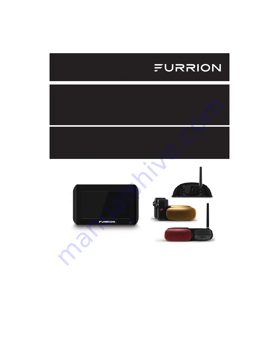
Furrion FOS05TADS Instruction Manual Download Page 1

5“ and 7” Vision S Camera System

Système de caméra Vision S de 5 et 7 po
Sistema de cámara Vision S de 5” y 7”

Instruction Manual
Manuel d’instructions
Manual de instrucciones

*  The packing contents may be different based on the kit you purchased. 

Please take the actual product as standard.

*  Le contenu de l’emballage peut être différent en fonction de la trousse 

achetée. Veuillez prendre le produit réel en référence.

*  Es posible que los contenidos del embalaje sean diferentes según el kit 

que haya comprado. Tome el producto real como estándar.

Models: FOS07TASK/FOS07TASR/FOS07TASE/FOS07TASF


FOS07TA

DS

/

FOS07TAED/FOS07TAPK/FOS07TAPT


FOS05TASK/FOS05TASR/FOS05TASE/FOS05TASF


FOS05TAEK/FOS05TAED/FOS05TAPK/FOS05TA

DS

Summary of Contents for FOS05TADS

Page 1: ...e the actual product as standard Le contenu de l emballage peut tre diff rent en fonction de la trousse achet e Veuillez prendre le produit r el en r f rence Es posible que los contenidos del embalaje...

Page 2: ...maintenance of the product Please keep this instruction manual in a safe place for future reference This will ensure safe use and reduce the risk of injury Be sure to pass on this manual to new owner...

Page 3: ...8 Installation 9 What s in the Box 9 Monitor Installation 9 Camera Installation 11 Installation 11 Electrical Connections 16 Getting Started 18 Activate the Monitor 18 Pairing the Camera and Monitor 1...

Page 4: ...the procedures in this instruction manual Improper installation or modification of this product will void all warranties Many jurisdictions have laws and regulations relating to the use of cameras and...

Page 5: ...ntee is not responsible for any changes or modifications not expressly approved by the party responsible for compliance Such modifications could void the user s authority to operate the equipment NOTE...

Page 6: ...erference and 2 this device must accept any interference including interference that may cause undesired operation of the device RF Exposure The device has been evaluated to meet general RF exposure r...

Page 7: ...replace existing safety procedures but rather to add an additional safety tool for your vehicle CAUTION Do not back up your vehicle while watching the monitor screen Always look in the direction the...

Page 8: ...rview Left Right Camera 12 IR LED Light LED Indicator Monitor Pairing Button Light Sensor Lens Traffic Light Front Rear Camera 8 IR LED LED Indicator Lens Monitor Pairing Button Light Sensor Traffic L...

Page 9: ...lock your view and complies with local laws for safe driving Do not place in an area where it might interfere with driving WARNING To prevent the risk of electric shock or fire during installation rem...

Page 10: ...ition where you are going to secure your monitor 2 Feed the supplied camera power cable through the hole on back of the tabletop bracket and insert into the monitor power port Fig 6 Fig 1 3 Align the...

Page 11: ...the vehicle or as close as is optimal Mount camera at least 2 inches above or below running lights Close proximity to lights may cause image blooming blurring and reduced night vision performance The...

Page 12: ...11 Fig 11 3 Feed the supplied 6 foot camera power cable through the gasket Ensure the bare end of the cable goes into the vehicle and the flat side faces inward Fig 12 Camera Power Cable Bracket Gask...

Page 13: ...Cover by unscrewing the four screws Fig 15 Fig 15 8 Pull out the camera power cable leaving approx 2 inches of slack Fig 16 Fig 16 9 Connect the camera power cable to the camera cable Fig 17 Fig 17 10...

Page 14: ...t is selected 1 Select a suitable position on the side of the vehicle wall where you would like to install the camera 2 Remove the lens cover by scratching the slot on the side of the traffic light Fi...

Page 15: ...talled onto the vehicle Fig 27 and Fig 28 Fig 27 Fig 28 8 Repeat steps 1 to 7 to install the other camera Front and Rear Camera Installation if purchased A traffic light must be installed together wit...

Page 16: ...g 31 Fig 31 5 Secure the traffic light base on the vehicle wall using four flat self tapping screws Fig 32 Fig 32 6 Insert the front or rear camera into the traffic light base and secure with the two...

Page 17: ...ystem can be connected to an electrical power source via a 7 Way Connector Wiring to running lights the camera will activate when the running lights are switched on Wiring to reverse lights the camera...

Page 18: ...utton to activate the menu setting page There are four options that allow you to set the wireless vehicle rear observation system before operating Touch one of the four options to enter the setting pa...

Page 19: ...essfully a red icon will appear after the device list 4 An icon indicates pairing failed repeat steps 2 and 3 to pair again 5 Repeat steps 1 to 4 to pair the other cameras 6 Refer to General Setup sec...

Page 20: ...set the cameras layout as QUAD SPLIT or H SPLIT The current selected setting will be highlighted in red 3 Press DOOR LEFT RIGHT or REAR to enable or disable one or more camera s as auto displaying cam...

Page 21: ...4 Repeat steps 2 and 3 to set the other camera VOLUME SETTING 1 Touch VOLUME on screen to enter the submenu 2 Press or to decrease or increase the volume or door and rear cameras AUTO DIM SETTING 1 T...

Page 22: ...onitor to recover display when LCD display off MOTION DETECT SETTING The motion detect function is used to detect objects in motion and assist in safe driving while the vehicle is in reverse When on t...

Page 23: ...omatically 2 Select the desired camera you are going to set 3 Touch to select BRIGHTNESS CONTRAST or COLOR and enter the submenu 4 Press or to change the settings 5 Repeat steps 2 to 4 to change the o...

Page 24: ...this is a wireless system the monitor is always watching for a video signal It is possible to receive signals from other cameras Systems such as security cameras baby monitors and even other back up...

Page 25: ...the left cam era Press to select the right camera Press to select the rear camera Press twice on the monitor screen to show the menu of control Icon Description Press to return to the quad rant mode...

Page 26: ...e of the monitor with a soft cloth moistened with water or glass cleaner Only clean the unit with a dry cloth Do not clean the unit with strong chemical agents or abrasive cleaners Never spill liquid...

Page 27: ...TICAL LENS Rear F2 0 Side F2 5 IR CUT FILTER 850nm automatic VIEW ANGLE Rear 120 Side 65 CURRENT IR ON 500mA 12V CURRENT IR OFF 350mA 12V CAMERA PIXEL 720x480 DISPLAY LCD POWER OFF 30mA 12V LCD BACKLI...

Page 28: ...n Camera and Monitor Large dense objects could be obscuring the signal If possible move the objects Interference from electrical appliances may be affecting the wireless signal Turn off the appliances...

Page 29: ...CE OF PRODUCT TO ANY DATA SOFTWARE OR INFORMATION AND NORMAL WEAR AND TEAR THIS WARRANTY ONLY PROTECTS THE ORIGINAL END USER YOU AND IS NOT TRANSFERABLE ANY ATTEMPT TO TRANSFER THIS WARRANTY SHALL MAK...

Page 30: ...ATION OF INCIDENTAL OR CONSEQUENTIAL DAMAGES OR EXCLUSIONS OR LIMITATIONS ON THE DURATION OF IMPLIED WARRANTIES OR CONDITIONS SO THE ABOVE LIMITATIONS OR EXCLUSIONS MAY NOT APPLY TO YOU THIS WARRANTY...

Page 31: ...toute s curit de l appareil Veuillez conserver le pr sent guide d utilisation en lieu s r pour vous y r f rer ult rieurement afin d assurer votre s curit et de r duire les risques de blessure Veuille...

Page 32: ...the equipment and receiver Connect the equipment into an outlet on a circuit different from that to which the receiver is connected Consult the dealer or an experienced radio TV technician for help Th...

Reviews: