


6-6
SPARC Enterprise M4000/M5000 Servers Service Manual • December 2010
6.1.5
Accessing the Hard Disk Drive Backplane of the
M4000 Server
Caution –
There is an electrical hazard if the power cords are not disconnected. All
power cords must be disconnected to completely remove power from the server.
Caution –
Use proper ESD grounding techniques when handling components. See
Section 1.1, “Safety Precautions” on page 1-1
.
1. Power off the server.
This step includes turning the key switch to the Service position, confirming that
the POWER LED is off, and disconnecting power cables. See
“Powering the Server Off Using Software” on page 4-12
Caution –
To prevent the equipment rack from tipping over, you must deploy the
antitilt feature, if applicable, before you slide the server out of the equipment rack.
Note –
When drawing out the SPARC Enterprise M4000/M5000 server to the front,
release the cable tie holding the PCI cables on the rear of the server.
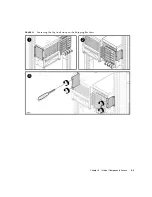
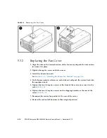
2. Remove the fan cover.
This step includes deploying the rack’s antitilt features (if applicable), sliding the
server out of the equipment rack, removing the 60-mm fan units and removing the
fan cover. See
Section 5.3.1, “Removing the Fan Cover” on page 5-8
6.1.6
Removing the Hard Disk Drive Backplane of the
M4000 Server
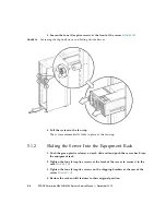
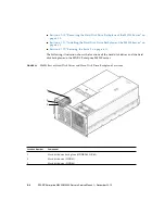
1. Remove the CD-RW/DVD-RW Drive Unit and place it on the ESD mat.
See
Section 6.2.3, “Removing the CD-RW/DVD-RW Drive Unit” on page 6-16
.
2. Remove the power and serial cables from the rear of the CD-RW/DVD-RW
Drive Backplane.
3. Loosen the captive screw that holds the rear of the CD-RW/DVD-RW Drive
Backplane in place.
4. Remove the CD-RW/DVD-RW backplane and place it on the ESD mat.
Summary of Contents for SPARC Enterprise M4000
Page 4: ......
Page 62: ...2 38 SPARC Enterprise M4000 M5000 Servers Service Manual December 2010 ...
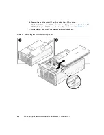
Page 89: ...Chapter 5 Internal Components Access 5 7 FIGURE 5 4 Removing the M5000 Server Top Cover ...
Page 126: ...6 34 SPARC Enterprise M4000 M5000 Servers Service Manual December 2010 ...
Page 132: ...7 6 SPARC Enterprise M4000 M5000 Servers Service Manual December 2010 ...
Page 158: ...8 26 SPARC Enterprise M4000 M5000 Servers Service Manual December 2010 ...
Page 245: ...Chapter 14 Backplane Unit Replacement 14 11 FIGURE 14 4 Removing the M5000 Server Backplane ...
Page 248: ...14 14 SPARC Enterprise M4000 M5000 Servers Service Manual December 2010 ...
Page 256: ...15 8 SPARC Enterprise M4000 M5000 Servers Service Manual December 2010 ...
Page 288: ...E 6 SPARC Enterprise M4000 M5000 Servers Service Manual December 2010 ...
Page 304: ...F 16 SPARC Enterprise M4000 M5000 Servers Service Manual December 2010 ...
Page 308: ...G 4 SPARC Enterprise M4000 M5000 Servers Service Manual December 2010 ...


