background image

Chapter 4

FRU Replacement Preparation

4-9

4.3.2

Verifying Hardware Operation

1. Type the

showhardconf

command to confirm the new component is installed.

EXAMPLE 4-3

showhardconf

XSCF> showhardconf

SPARC Enterprise M5000;

    + Serial:BCF07500B6; Operator_Panel_Switch:Locked;

    + Power_Supply_System:Dual; SCF-ID:XSCF#0;

    + System_Power:On; System_Phase:Cabinet Power On;

    Domain#0 Domain_Status:Initialization Phase;

    Domain#1 Domain_Status:Initialization Phase;

 MBU_B Status:Normal; Ver:0201h; Serial:BC07490823  ;

+ FRU-Part-Number:CF00541-0478 05

/541-0478-05

;

        + Memory_Size:64 GB;

CPUM#0-CHIP#0 Status:Normal; Ver:0501h; Serial:PP0723016Q

;

+ FRU-Part-Number:CA06761-D204 A0

/LGA-JUPP-01

;

            + Freq:2.530 GHz; Type:32;

            + Core:4; Strand:2;

                   :

CPUM#3-CHIP#1 Status:Normal; Ver:0501h; Serial:PP074804E9

;

+ FRU-Part-Number:CA06761-D204 A0

/LGA-JUPP-01

;

            + Freq:2.530 GHz; Type:32;

            + Core:4; Strand:2;

        MEMB#0 Status:Normal; Ver:0101h; Serial:BF09061G0E  ;

+ FRU-Part-Number:CF00541-0545 06

/541-0545-06

;

            MEM#0A Status:Normal;

+ Code:c1000000000000005372T128000HR3.7A

356d-0d016912;

                + Type:1A; Size:1 GB;

                   :

            MEM#3B Status:Normal;

+ Code:c1000000000000004572T128000HR3.7A

252b-04123424;

                + Type:1A; Size:1 GB;

                   :

 MEMB#7 Status:Normal; Ver:0101h; Serial:BF09061GBA  ;

+ FRU-Part-Number:CF00541-0545 06

/541-0545-06

;

            MEM#0A Status:Normal;

+ Code:2cffffffffffffff0818HTF12872Y-53EB3 0300-d504600c;

                + Type:1A; Size:1 GB;

                   :

            MEM#3B Status:Normal;

+ Code:7f7ffe00000000004aEBE10RD4AGFA-5C-E 3020-2229c19c;

                + Type:1A; Size:1 GB;

Summary of Contents for SPARC Enterprise M4000

Page 1: ...SPARC Enterprise M4000 M5000 Servers Service Manual Part No 819 2210 14 Manual Code C120 E352 07EN December 2010 Revision A ...

Page 2: ...tered trademarks of Fujitsu Limited All SPARC trademarks are used under license and are registered trademarks of SPARC International Inc in the U S and other countries Products bearing SPARC trademarks are based upon architectures developed by Oracle and or its affiliates SPARC64 is a trademark of SPARC International Inc used under license by Fujitsu Microelectronics Inc and Fujitsu Limited Other ...

Page 3: ...es déposées de Fujitsu Limited Toutes les marques SPARC sont utilisées sous licence et sont des marques déposées de SPARC International Inc aux États Unis et dans d autres pays Les produits portant la marque SPARC reposent sur des architectures développées par Oracle et ou ses sociétés affiliées SPARC64 est une marque de SPARC International Inc utilisée sous licence par Fujitsu Microelectronics In...

Page 4: ......

Page 5: ... Fault Isolation 2 1 2 1 Determining Which Diagnostics Tools to Use 2 1 2 2 Checking the Server and System Configuration 2 4 2 2 1 Checking the Hardware Configuration and FRU Status 2 4 2 2 1 1 Checking the Hardware Configuration 2 5 2 2 2 Checking the Software and Firmware Configuration 2 6 2 2 2 1 Checking the Software Configuration 2 7 2 2 2 2 Checking the Firmware Configuration 2 7 2 2 3 Downl...

Page 6: ...d 2 23 2 6 3 Using the fmadm faulty Command 2 23 2 6 3 1 fmadm repair Command 2 23 2 6 3 2 fmadm config Command 2 24 2 6 4 Using the fmstat Command 2 24 2 7 Traditional Oracle Solaris Diagnostic Commands 2 25 2 7 1 Using the iostat Command 2 26 2 7 1 1 Options 2 26 2 7 2 Using the prtdiag Command 2 27 2 7 2 1 Options 2 27 2 7 3 Using the prtconf Command 2 30 2 7 3 1 Options 2 30 2 7 4 Using the ne...

Page 7: ...on 4 6 4 3 Hot Replacement 4 6 4 3 1 Removing and Replacing a FRU 4 7 4 3 2 Verifying Hardware Operation 4 9 4 4 Cold Replacement Powering the Server Off and On 4 12 4 4 1 Powering the Server Off Using Software 4 12 4 4 2 Powering the Server On Using Software 4 13 4 4 3 Powering the Server Off Manually 4 14 4 4 4 Powering the Server On Manually 4 14 4 4 5 Verifying Hardware Operation 4 15 5 Intern...

Page 8: ...rd Disk Drive Backplane of the M4000 Server 6 6 6 1 7 Installing the Hard Disk Drive Backplane of the M4000 Server 6 7 6 1 8 Securing the Server 6 8 6 1 9 Accessing the Hard Disk Drive Backplane of the M5000 Server 6 9 6 1 10 Removing the Hard Disk Drive Backplane of the M5000 Server 6 10 6 1 11 Installing the Hard Disk Drive Backplane of the M5000 Server 6 10 6 1 12 Securing the Server 6 11 6 2 C...

Page 9: ...pe Drive Unit 6 26 6 3 3 Installing the Tape Drive Unit 6 27 6 3 4 Securing the Server 6 27 6 3 5 Accessing the Tape Drive Backplane of the M4000 Server 6 28 6 3 6 Removing the Tape Drive Backplane of the M4000 Server 6 29 6 3 7 Installing the Tape Drive Backplane of the M4000 Server 6 29 6 3 8 Securing the Server 6 30 6 3 9 Accessing the Tape Drive Backplane of the M5000 Server 6 31 6 3 10 Removi...

Page 10: ...cessing the I O Unit 8 10 8 3 2 Removing the I O Unit 8 10 8 3 3 Installing the I O Unit 8 11 8 3 4 Securing the Server 8 12 8 4 I O Unit DC DC Converter Replacement 8 12 8 4 1 Accessing the I O Unit DC DC Converter DDC_A 0 or DDC_B 0 8 14 8 4 2 Removing the I O Unit DC DC Converter DDC_A 0 or DDC_B 0 8 14 8 4 3 Installing the I O Unit DC DC Converter DDC_A 0 or DDC_B 0 8 17 8 4 4 Securing the Ser...

Page 11: ...lling the 172 mm Fan Module 10 9 10 1 8 Securing the Server 10 9 10 1 9 Accessing the 60 mm Fan Backplane 10 10 10 1 10 Removing the 60 mm Fan Backplane 10 11 10 1 11 Installing the 60 mm Fan Backplane 10 12 10 1 12 Securing the Server 10 12 10 1 13 Accessing the SPARC Enterprise M4000 172 mm Fan Backplane 10 13 10 1 14 Removing the SPARC Enterprise M4000 172 mm Fan Backplane 10 13 10 1 15 Install...

Page 12: ...2 4 Accessing the DIMMs 11 10 11 2 5 Removing the DIMMs 11 11 11 2 6 Installing the DIMMs 11 12 11 2 7 Securing the Server 11 12 12 CPU Module Replacement 12 1 12 1 CPU Module Replacement 12 1 12 1 1 Accessing the CPU Module 12 4 12 1 2 Removing the CPU Module 12 5 12 1 3 Installing the CPU Module 12 6 12 1 4 Securing the Server 12 6 12 2 CPU Upgrade 12 7 12 2 1 SPARC64 VII SPARC64 VII CPU Modules...

Page 13: ...he M5000 Server Motherboard Unit 13 8 13 1 7 Installing the M5000 Server Motherboard Unit 13 10 13 1 8 Securing the Server 13 11 13 2 DC DC Converter Replacement 13 12 13 2 1 Accessing the M4000 Server DC DC Converter 13 14 13 2 2 Removing the M4000 Server DC DC Converter 13 15 13 2 3 Installing the M4000 Server DC DC Converter 13 16 13 2 4 Securing the Server 13 16 13 2 5 Accessing the M5000 Serv...

Page 14: ...ckplane Unit 14 10 14 1 7 Installing the M5000 Server Backplane Unit 14 12 14 1 8 Securing the Server 14 12 15 Operator Panel Replacement 15 1 15 1 Operator Panel Replacement 15 1 15 2 Accessing the Operator Panel 15 4 15 2 1 Removing the Operator Panel 15 4 15 2 2 Installing the Operator Panel 15 7 15 2 3 Securing the Server 15 7 A Components List A 1 B Rules for System Configuration B 1 B 1 Serv...

Page 15: ... Connection Diagram for Serial Cable D 4 E UPS Controller E 1 E 1 Overview E 1 E 2 Signal Cables E 1 E 3 Signal Line Configuration E 2 E 4 Power Supply Conditions E 3 E 4 1 Input circuit E 3 E 4 2 Output circuit E 4 E 5 UPS Cable E 4 E 6 UPC Connector E 5 F Air Filters F 1 F 1 M4000 and M5000 Servers Air Filter F 2 F 1 1 Command Operations Procedures F 2 F 2 Air Filter Installation for the M4000 S...

Page 16: ...xvi SPARC Enterprise M4000 M5000 Servers Service Manual December 2010 F 3 1 Removing the Air Filter from the M5000 Server F 13 F 3 2 Servicing the Air Filter F 14 G Abbreviations G 1 Index Index 1 ...

Page 17: ...maintenance providers who have received formal service training A single engineer service model is used for servicing SPARC Enterprise M4000 M5000 midrange servers with one exception When the motherboard of a SPARC Enterprise M5000 server must be removed and that server is mounted above waist high in the rack then two engineers or a platform must be used for safety This section explains SPARC Ente...

Page 18: ...5000 Servers Overview Guide 819 2204 C120 E346 SPARC Enterprise M3000 M4000 M5000 M8000 M9000 Servers Important Legal and Safety Information 821 2098 C120 E633 SPARC Enterprise M4000 M5000 Servers Safety and Compliance Manual 819 2203 C120 E348 External I O Expansion Unit Safety and Compliance Guide 819 1143 C120 E457 SPARC Enterprise M4000 Server Unpacking Guide 821 3043 C120 E349 SPARC Enterpris...

Page 19: ... Enterprise M3000 M4000 M5000 M8000 M9000 Servers Glossary 821 2800 C120 E514 All getting started guides are printed documents For XCP version 1100 or later Fonts symbols Meaning Example AaBbCc123 What you type when contrasted with on screen computer output This font represents the example of command input in the frame XSCF adduser jsmith AaBbCc123 The names of commands files and directories on sc...

Page 20: ...tion SPARC Enterprise M4000 M5000 Servers Safety and Compliance Guide Documentation Feedback If you have any comments or requests regarding this document go to the following web sites For Oracle users http docs sun com For Fujitsu users in U S A Canada and Mexico http www computers us fujitsu com www support_servers shtml s upport servers For Fujitsu users in other countries refer to this SPARC En...

Page 21: ...rist or foot strap Electrostatic Discharge ESD Connect the ESD connector to your server and wear the wrist strap or foot strap when handling printed circuit boards There are two antistatic strap attachment points on the chassis 1 Right side towards the front 2 Left side towards the rear ESD mat ESD An approved ESD mat provides protection from static damage when used with a wrist strap or foot stra...

Page 22: ... out components that could result in fire or electric shock Refer servicing of equipment to qualified personnel 1 2 1 Electrical Safety Precautions Ensure that the voltage and frequency of the power outlet to be used match the electrical rating labels on the equipment Wear antistatic wrist straps when handling any magnetic storage devices system boards or other printed circuit boards Use only prop...

Page 23: ...d the forces upon it when the server is extended on its slides The normal procedure in this case would be to fix the rack through the raised floor to the concrete floor below using a proprietary mounting kit for the purpose Caution If more than one server is installed in an equipment rack service only one server at a time 1 2 3 Filler Boards and Filler Panels Filler boards and panels which are phy...

Page 24: ... of the board Do not use an oscilloscope probe on the components The soldered pins are easily damaged or shorted by the probe point Transport the board in its packaging box Caution The heat sinks can be damaged by incorrect handling Do not touch the heat sinks while replacing or removing boards If a heat sink is loose or broken obtain a replacement board When storing or shipping a board ensure tha...

Page 25: ...on 2 3 Operator Panel on page 2 8 Section 2 4 Error Conditions on page 2 14 Section 2 5 LED Functions on page 2 18 Section 2 6 Using the Diagnostic Commands on page 2 21 Section 2 7 Traditional Oracle Solaris Diagnostic Commands on page 2 25 Section 2 8 Other Issues on page 2 37 2 1 Determining Which Diagnostics Tools to Use When a failure occurs a message is often displayed on the monitor Use the...

Page 26: ...2 2 SPARC Enterprise M4000 M5000 Servers Service Manual December 2010 FIGURE 2 1 Diagnostic Method Flow Chart No ...

Page 27: ...Chapter 2 Fault Isolation 2 3 FIGURE 2 2 Diagnostic Method Flow Chart Traditional Data Collection ...

Page 28: ...t display the mark The administrative console should not display error messages The server processor logs should not display any error messages The Oracle Solaris Operating System message files should not indicate any additional errors 2 2 1 Checking the Hardware Configuration and FRU Status To replace a faulty component and perform the maintenance on the server it is important to check and unders...

Page 29: ... terminal 1 Log in with the account of the XSCF hardware maintenance engineer 2 Type showhardconf The showhardconf command prints the hardware configuration information to the screen See the SPARC Enterprise M3000 M4000 M5000 M8000 M9000 Servers XSCF User s Guide for more detailed information TABLE 2 1 Commands for Checking Hardware Configuration Command Description showhardconf Displays hardware ...

Page 30: ... Servers XSCF User s Guide for more detailed information Check the software and firmware configuration information with assistance from the system administrator However if you have received login authority from the system administrator the commands shown in the table can be used from the maintenance terminal for these checks TABLE 2 2 Commands for Checking Software and Firmware Configuration Comma...

Page 31: ...ARC Enterprise M3000 M4000 M5000 M8000 M9000 Servers XSCF User s Guide for more detailed information showboards 8 XSCF Shell command that indicates information on eXtended system board XSB It can indicate information on XSB that belongs to the specified domain and information on all XSBs mounted The eXtended System Board XSB combines the hardware resources of a physical system board The SPARC Ente...

Page 32: ...e terminal to download Error Log information over the XSCF LAN 2 3 Operator Panel When no network connection is available the operator panel is used to start or stop the server The operator panel displays three LED status indicators a Power switch and a security keyswitch The panel is located on the front of the server in the upper right When the server is running the Power and XSCF STANDBY LEDs g...

Page 33: ...2 Fault Isolation 2 9 FIGURE 2 3 M4000 Server Operator Panel l Location Number Component 1 POWER LED 2 XSCF STANDBY LED 3 CHECK LED 4 Power switch 5 Mode switch keyswitch 6 Antistatic ground socket 1 2 3 4 5 6 ...

Page 34: ...nel Additional LEDs are located in various locations in the server For more information about LED indicator locations see Section 2 5 LED Functions on page 2 18 Location Number Component 1 POWER LED 2 XSCF STANDBY LED 3 CHECK LED 4 Power switch 5 Mode switch keyswitch 6 Antistatic ground socket 1 2 3 4 5 6 ...

Page 35: ... on process CHECK LED Amber Indicates that server detected a fault On Error detected that disables the startup Off Normal or server power off power failure Blinking Indicates the position of fault Power switch Switch to direct server power on power off Mode switch keyswitch The Locked setting Normal key position Power on is available with the Power switch but power off is not Disables the Power sw...

Page 36: ...r is switched off Off Off On The circuit breaker is switched on Off Blinking Off The XSCF is being initialized Off Blinking On An error occurred in the XSCF Off On Off The XSCF is on standby The system is waiting for power on of the air conditioning system On On Off Warm up standby processing is in progress power on is delayed The power on sequence is in progress The system is in operation Blinkin...

Page 37: ... performed in Service mode while the server is stopped Because remote power control and automatic power control of the server are disabled in Service mode unintentional power on can be prevented Power switch Used to control the server power Power on and power off are controlled by pressing this switch in different patterns as described below Holding down for a short time less than 4 seconds Regard...

Page 38: ...ware and hardware fault conditions This new technology lessens the time required to debug a hardware or software problem and provides the administrator and technical support with detailed data about each fault 2 4 1 Predictive Self Healing Tools In the Solaris 10 software the fault manager runs in the background If a failure occurs the system software recognizes the error and attempts to determine...

Page 39: ...fault in addition to populating the system console messages with more details TABLE 2 7 shows a typical message generated when a fault occurs The message appears on your console and is recorded in the var adm messages file Note The message in TABLE 2 7 indicates that the fault has already been diagnosed Any corrective action that the system can perform has already taken place If your server is sti...

Page 40: ...0 20 dt88 292 A problem was detected in the PCI Express subsystem DESC A basic description of the failure Nov 1 16 30 20 dt88 292 Refer to http sun com msg SUN4 8000 0Y for more information WEB SITE Where to find specific information and actions for this fault Nov 1 16 30 20 dt88 292 AUTO RESPONSE One or more device instances may be disabled AUTO RESPONSE What if anything the system did to allevia...

Page 41: ... Command Operand Description showlogs 8 console Displays console of Domain monitor Logs messages that are displayed in the message window panic Logs output to the console during a panic ipl Collects console data generated during the period of the power on of a domain to the completion of the operating system start TABLE 2 9 Commands for Checking the Messaging Output Command Operand Description sho...

Page 42: ...M9000 Servers XSCF User s Guide for more detailed information TABLE 2 10 describes the LEDs and their functions TABLE 2 10 Component LEDs LED Name Display and Meaning READY green Indicates whether the component is operating On Indicates that the component is operating The component cannot be disconnected and removed from the server while the READY LED is On Blinking Indicates that the component is...

Page 43: ...hrough the LAN port LINK SPEED On amber Indicates that the communication speed for the LAN port is 1G bps On green Indicates that the communication speed for the LAN port is 100M bps Off Indicates that the communication speed for the LAN port is 10M bps PCI slot POWER On green Indicates that the power to the PCI slot is turned on The PCI card cannot be removed Off Indicates that the power to the P...

Page 44: ...the normal state of the power supply unit LED_AC On green Power supply unit has AC applied and is supplying 12V Off Indicates that AC is out of the specified operating range and 12V is not being supplied from the power supply unit LED_DC On green Power supply unit has AC applied and is supplying 48V Standby pinhole provides a manual backup to turn off 48V power Off Indicates that 48V is not being ...

Page 45: ...6 1 Using the showlogs Command The showlogs command displays the contents of a specified log in order of time stamp starting with the oldest date The showlogs command displays the following logs error log power log event log temperature and humidity record monitoring message log console message log panic message log IPL message log An example of the showlogs output XSCF showlogs error Date Oct 03 ...

Page 46: ... The second line is a declaration of the certainty of the diagnosis In this case we are 100 percent sure the failure is in the ASIC described If the diagnosis might involve multiple components you might see two lines here with 50 in each for example The FRU line declares the part that needs to be replaced to return the server to a fully operational state The rsrc line describes which component was...

Page 47: ... device is degraded and is associated with the same UUID as seen above You might also see faulted states 2 6 3 1 fmadm repair Command If fmadm faulty occurs the faulty FRU CPU memory or I O unit is replaced and then the fmadm repair command needs to be executed to clear FRU information on the domain If the fmadam repair command is not executed error messages continue to be output XSCF fmdump e TIM...

Page 48: ...ciated with the Oracle Solaris fault manager The fmstat command shows information about DE performance In the example below the fmd self diagnosis DE also seen in the console output has received an event which it accepted A case is opened for that event and a diagnosis is performed to solve the cause for the failure See the following example fmadm repair STATERESOURCE UUID degraded dev pci 1e 6000...

Page 49: ...ge 2 34 Using the ps Command on page 2 35 Using the prstat Command on page 2 36 Most of these commands are located in the usr bin or usr sbin directories Note For additional details options examples and the most up to date information for each command refer to that command s man page XSCF fmstat module ev_recv ev_acpt wait svc_t w b open solve memsz bufsz eft 0 0 0 0 0 0 0 0 0 0 3 3M 0 event trans...

Page 50: ...ulated errors Identifies suspect I O devices E Displays all device error statistics Provides information about devices manufacturer model number serial number size and errors n Displays names in descriptive format Descriptive format helps identify devices x For each drive reports extended drive statistics The output is in tabular form Similar to the e option but provides rate information This help...

Page 51: ...hat identified elsewhere in this document This is normal 2 7 2 1 Options TABLE 2 13 describes options for the prtdiag command and how those options can help troubleshooting TABLE 2 13 Options for prtdiag Option Description How It Can Help No option Lists components Identifies CPU timing and PCI cards installed v Verbose mode Displays the time of the most recent AC power failure and the most recent...

Page 52: ...59 60 61 62 63 2660 11 0 7 192 Memory Configuration Memory Available Memory DIMM of Mirror Interleave LSB Group Size Status Size DIMMs Mode Factor 00 A 65536MB okay 4096MB 16 no 8 way 00 B 65536MB okay 4096MB 16 no 8 way 01 A 65536MB okay 4096MB 16 no 8 way 01 B 65536MB okay 4096MB 16 no 8 way IO Devices IO Lane Frq LSB Type LPID RvID DvID VnID BDF State Act Max Name Model Logical Path 00 PCIe 0 b...

Page 53: ... 8532 NA pci 10 600000 pci 0 pci 8 01 PCIe 16 bc 8532 10b5 3 9 0 okay 1 8 pci pciex10b5 8532 NA pci 10 600000 pci 0 pci 9 01 PCIx 16 8 125 1033 4 0 0 okay 100 133 pci pciexclass 060400 NA pci 10 600000 pci 0 pci 8 pci 0 01 PCIx 16 8 125 1033 4 0 1 okay 133 pci pciexclass 060400 NA pci 10 600000 pci 0 pci 8 pci 0 1 01 PCIx 16 2 50 1000 5 1 0 okay 133 scsi pci1000 50 LSI 1064 pci 10 600000 pci 0 pci...

Page 54: ...4 Options for prtconf Option Description How It Can Help No option Displays the device tree of devices recognized by the OS If a hardware device is recognized then it is probably functioning properly If the message driver not attached is displayed for the device or for a sub device then the driver for the device is corrupt or missing D Similar to the output of no option however the device driver i...

Page 55: ...ed core driver not attached cpu driver not attached cpu driver not attached core driver not attached cpu driver not attached cpu driver not attached cmp driver not attached core driver not attached cpu driver not attached cpu driver not attached core driver not attached cpu driver not attached cpu driver not attached pci instance 0 ebus instance 0 flashprom driver not attached serial instance 0 sc...

Page 56: ...ce 1 fp driver not attached disk driver not attached fp instance 0 pci instance 1 pci instance 15 pci instance 16 pci instance 25 pci instance 31 pci instance 32 pci instance 33 pci instance 18 pci instance 29 pci instance 34 pci instance 35 pci instance 36 pci instance 2 pci instance 5 pci instance 6 pci instance 7 pci instance 8 pci instance 9 pci instance 10 pci instance 11 pci instance 12 pci ...

Page 57: ...all at once p Displays the media table Provides MAC address for hosts on the subnet r Displays the routing table Provides routing information n Replaces host names with IP addresses Used when an address is more useful than a host name netstat p Net to Media Table IPv4 Device IP Address Mask Flags Phys Addr bge0 san ff1 14 a 255 255 255 255 o 00 14 4f 3a 93 61 bge0 san ff2 40 a 255 255 255 255 o 00...

Page 58: ...se individual routes can be tested for quality i interface Designates which interface to send and receive the probe packet through Enables a simple check of secondary network interfaces n Replaces host names with IP addresses Used when an address is more beneficial than a host name s Pings continuously in one second intervals Ctrl C aborts Upon abort statistics are displayed Helps identify intermi...

Page 59: ...E 2 17 Options for ps Option Description How It Can Help e Displays information for every process Identifies the process ID and the executable f Generates a full listing Provides the following process information user ID parent process ID time when executed and the path to the executable o option Enables configurable output The pid pcpu pmem and comm options display process ID percent CPU consumpt...

Page 60: ...he terminal window and the total number of processes Output is automatically updated every five seconds Ctrl C aborts Output identifies process ID user ID memory used state CPU consumption and command name n number Limits output to number of lines Limits amount of data displayed and identifies primary resource consumers s key Permits sorting list by key parameter Useful keys are cpu default time a...

Page 61: ...problem results in the showdisk command failing to display the boot disk and the bootdisk command displaying the console message Can t locate boot device When this occurs remove the PCI PCI X card in slot 0 to see if the boot issue is remedied If the IO unit is fully stocked and it is not possible to remove the PCI PCI X card then you should attempt to place another card in slot 0 if possible If t...

Page 62: ...2 38 SPARC Enterprise M4000 M5000 Servers Service Manual December 2010 ...

Page 63: ...cleaning procedure Note Contact your sales representative for tape drive unit options on M4000 and M5000 servers 3 1 1 Cleaning the Tape Drive Unit To avoid the Clean Lamp from prematurely illuminating the following maintenance rules should be followed Clean your tape drive unit once every 5 to 24 hours of continuous use or once a week Clean your tape drive unit once a month even if it is not in u...

Page 64: ...n the following states Off Lit and Blinking Remove the cassette before turning the power OFF The tape life might be shortened or a malfunction might occur during the backup process if the power is turned OFF while the cassette is still inside Note If the cleaning lamp starts blinking immediately after completion of a cleaning operation the data cassette might have been damaged In this case replace...

Page 65: ...t the FRU be inactivated or powered down using either an XSCF command or Oracle Solaris OS command Because the power supply unit PSU and fan unit FAN do not belong to any domain they are operated by using XSCF commands regardless of the operating state of the Oracle Solaris OS Note The procedure for isolating the hard disk drive from the Oracle Solaris OS varies depending on whether disk mirroring...

Page 66: ...unit PSU Front Active replacement replacefru Hot replacement replacefru Cold replacement 172 mm fans FAN_A Top Active replacement replacefru Hot replacement replacefru Cold replacement 60 mm fans FAN_B Top Active replacement replacefru Hot replacement replacefru Cold replacement Tape drive unit TAPEU Front Active replacement Hot replacement Cold replacement I O unit IOU Rear Cold replacement I O u...

Page 67: ...rol facility unit XSCFU Rear Cold replacement Hard disk drive backplane HDDBP Top Cold replacement CD RW DVD RW backplane Top Cold replacement Tape drive backplane TAPEBP Top Cold replacement Operator panel OPNL Top Cold replacement When using active replacement for a PSU only one power supply unit should be replaced at a time to ensure redundancy When using active replacement for a 172 mm or 60 m...

Page 68: ...have to be replaced using cold replacement procedures However active replacement can be used if the boot disk can be isolated from the Oracle Solaris OS by disk mirroring software and other software 4 2 1 Removing a FRU From a Domain Note Before you remove a PCI cassette make sure that there is no I O activity on the card in the cassette 1 From the Oracle Solaris prompt type the cfgadm command to ...

Page 69: ... 3 Type the cfgadm command to confirm the component is now disconnected 4 2 2 Removing and Replacing a FRU Once the FRU has been removed from the domain see Section 4 3 1 Removing and Replacing a FRU on page 4 7 4 2 3 Adding a FRU Into a Domain 1 From the Oracle Solaris prompt type the cfgadm command to connect the component to the domain The Ap_Id is shown in the output of cfgadm iou 0 pci 0 for ...

Page 70: ...owever active replacement can be used if the boot disk can be isolated from the Oracle Solaris OS by disk mirroring software and other software 4 3 Hot Replacement In hot replacement the Oracle Solaris OS does not need to be configured to allow the component to be replaced Depending on the FRU to be replaced the FRU can either be directly replaced or be inactivated or powered down using an XSCF co...

Page 71: ...d 1 FAN Fan Unit 2 PSU Power Supply Unit Select 1 2 c cancel 1 Maintenance Replacement Menu Please select a FAN to be replaced No FRU Status 1 FAN_A 0 Faulted 2 FAN_A 1 Normal 3 FAN_A 2 Normal 4 FAN_A 3 Normal Select 1 4 b back 1 You are about to replace FAN_A 0 Do you want to continue r replace c cancel r Please confirm the CHECK LED is blinking If this is the case please replace FAN_A 0 After re...

Page 72: ... to the XSCF Shell prompt Refer to the replacefru man page for more information EXAMPLE 4 2 replacefru command status Diagnostic tests of FAN_A 0 is started This operation may take up to 2 minute s progress scale reported in seconds 0 30 60 90 done Maintenance Replacement Menu Status of the replaced unit FRU Status FAN_A 0 Normal The replacement of FAN_A 0 has completed normally f finish f Mainten...

Page 73: ...l PP0723016Q FRU Part Number CA06761 D204 A0 LGA JUPP 01 Freq 2 530 GHz Type 32 Core 4 Strand 2 CPUM 3 CHIP 1 Status Normal Ver 0501h Serial PP074804E9 FRU Part Number CA06761 D204 A0 LGA JUPP 01 Freq 2 530 GHz Type 32 Core 4 Strand 2 MEMB 0 Status Normal Ver 0101h Serial BF09061G0E FRU Part Number CF00541 0545 06 541 0545 06 MEM 0A Status Normal Code c1000000000000005372T128000HR3 7A 356d 0d01691...

Page 74: ... BF073226HP FRU Part Number CF00541 4361 01 541 4361 01 Type 1 DDC_A 0 Status Normal DDCR Status Normal DDC_B 0 Status Normal XSCFU Status Normal Active Ver 0101h Serial BF07435D98 FRU Part Number CF00541 0481 04 541 0481 04 OPNL Status Normal Ver 0101h Serial BF0747690D FRU Part Number CF00541 0850 06 541 0850 06 PSU 0 Status Normal Serial 0017527 0738063762 FRU Part Number CF00300 1898 0350 300 ...

Page 75: ... for more information 3 Verify the state of the status LEDs on the FRU Refer to TABLE 2 11 for LED status EXAMPLE 4 5 showhardconf u XSCF showhardconf u SPARC Enterprise M5000 Memory_Size 64 GB FRU Quantity MBU_B 1 CPUM 4 Freq 2 530 GHz 8 MEMB 8 MEM 64 Type 1A Size 1 GB 64 DDC_A 4 DDC_B 2 IOU 2 DDC_A 2 DDCR 2 DDC_B 2 XSCFU 1 OPNL 1 PSU 4 FANBP_C 1 FAN_A 4 ...

Page 76: ...emoved make certain to allow 30 seconds before connecting the power cords back into the chassis 4 4 1 Powering the Server Off Using Software 1 Notify users that the server is being powered off 2 Back up the system files and data to tape if necessary 3 Log in to the XSCF Shell and type the poweroff command The following actions occur when the poweroff command is used The Oracle Solaris OS shuts dow...

Page 77: ... On 4 Turn the keyswitch on the operator panel to the desired mode position Locked or Service 5 Log into the XSCF Shell and type the poweron command Refer to the SPARC Enterprise M3000 M4000 M5000 M8000 M9000 Servers XSCF User s Guide for details 6 After a delay the following activities occur The operator panel POWER LED lights The system executes the power on self test POST Then the server is com...

Page 78: ... be disconnected to completely remove power from the server 4 4 4 Powering the Server On Manually 1 Make sure that the server has enough power supply units to run the desired configuration 2 Connect all power cables to the input power source 3 Make sure the XSCF STANDBY LED is On 4 Turn the keyswitch on the operator panel to the desired mode position Locked or Service 5 Press the Power switch on t...

Page 79: ...8 FRU Part Number CF00375 3477 50 375 3477 50 Freq 2 150 GHz Type 16 Core 2 Strand 2 CPUM 0 CHIP 1 Status Normal Ver 0201h Serial PP0629L068 FRU Part Number CF00375 3477 50 375 3477 500 Freq 2 150 GHz Type 16 Core 2 Strand 2 MEMB 0 Status Normal Ver 0101h Serial 01068 FRU Part Number CF00541 0545 01 541 0545 01 MEM 0A Status Normal Code c1000000000000004572T128000HR3 7A 252b 04123520 Type 1B Size ...

Page 80: ... Normal Active Ver 0101h Serial 78670002628 FRU Part Number CF00541 0481 01 541 0481 01 OPNL Status Normal Ver 0101h Serial 78670000878 FRU Part Number CF00541 0850 01 541 0850 01 PSU 0 Status Normal Serial XF0345 3 FRU Part Number CF00300 1898 50 300 1898 50 Power_Status Off AC 200 V PSU 1 Status Normal Serial XF0346 FRU Part Number CF00300 1898 50 300 1898 50 Power_Status Off AC 200 V PSU 2 Stat...

Page 81: ... pci 0 pci 8 pci 0 1 ethernet 1 pci 40 600000 pci 0 pci 8 pci 0 network 2 1 pci 40 600000 pci 0 pci 8 pci 0 network 2 pci 40 600000 pci 0 pci 8 pci 0 scsi 1 pci 40 600000 pci 0 pci 8 pci 0 scsi 1 disk pci 40 600000 pci 0 pci 8 pci 0 scsi 1 tape pci 48 4000 ebus 1 pci 48 4000 ebus 1 panel 14 280030 pci 48 4000 ebus 1 scfc 14 200000 pci 48 4000 ebus 1 serial 14 400000 pci 48 4000 ebus 1 flashprom 10...

Page 82: ...i all ok probe scsi all pci 0 600000 pci 0 pci 8 pci 0 scsi 1 MPT Version 1 05 Firmware Version 1 07 00 00 Target 0 Unit 0 Disk SEAGATE ST973401LSUN72G 0556 143374738 Blocks 73 GB SASAddress 5000c5000092beb9 PhyNum 0 Target 1 Unit 0 Disk SEAGATE ST973401LSUN72G 0556 143374738 Blocks 73 GB SASAddress 5000c500002eeaf9 PhyNum 1 Target 3 Unit 0 Removable Read Only device TSSTcorpCD DVDW TS L532USR01 S...

Page 83: ...5 1 Section 5 2 Top Cover Remove and Replace on page 5 5 Section 5 3 Fan Cover Remove and Replace on page 5 8 5 1 Sliding the Server In and Out to the Fan Stop The slide rails have two designated lock points The first the fan stop is for easy access to the fan units The fan units are hot active or cold replacement components When using active replacement only one fan unit should be replaced at a t...

Page 84: ...n drawing out the SPARC Enterprise M4000 M5000 Server to the front release the cable tie holding the PCI cables on the rear of the server Caution Use proper ESD grounding techniques when handling components See Section 1 1 Safety Precautions on page 1 1 1 Deploy the rack s antitilt features if applicable Refer to the manual that shipped with the rack for details on antitilt features 2 If shipping ...

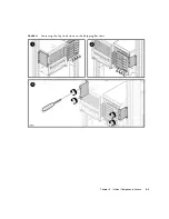
Page 85: ...Chapter 5 Internal Components Access 5 3 FIGURE 5 1 Loosening the Captive Screws on the Shipping Brackets ...

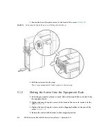
Page 86: ...automatically locks in place at the fan stop 5 1 2 Sliding the Server Into the Equipment Rack 1 Push the green plastic releases on each slide rail and push the server back into the equipment rack 2 Tighten the four 4 captive screws at the front of the server to secure it in the rack FIGURE 5 2 3 Tighten the four 4 captive screws on the shipping brackets at the rear of the server FIGURE 5 1 4 Resto...

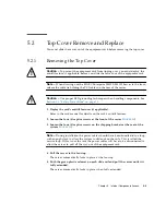
Page 87: ...ntitilt features if applicable Refer to the rack manual for details on the rack s antitilt features 2 Loosen the four 4 captive screws at the front of the server FIGURE 5 2 3 Loosen the four 4 captive screws on the shipping brackets at the rear of the system FIGURE 5 1 Note During installation the power cables should have been bundled into a loop with enough slack to allow the system to slide out ...

Page 88: ...tive screw s on the center top of the server The SPARC Enterprise M4000 server has one 1 captive screw FIGURE 5 1 The SPARC Enterprise M5000 server has two 2 captive screws FIGURE 5 4 7 Slide the top cover towards the rear and then remove it FIGURE 5 3 Removing the M4000 Server Top Cover ...

Page 89: ...Chapter 5 Internal Components Access 5 7 FIGURE 5 4 Removing the M5000 Server Top Cover ...

Page 90: ...Tighten the four 4 captive screws on the shipping brackets at the rear of the server FIGURE 5 1 6 Reconnect the service loop cables to the rear of the server 7 Restore the rack antitilt features to their original position 5 3 Fan Cover Remove and Replace All internal components are cold replacement components The server must be powered off and power cables disconnected from the input power source ...

Page 91: ... Note During installation the power cables should have been bundled into a loop with enough slack to allow the system to slide out on the rails This is called the service loop If this is not the case the power cables will have to be disconnected to allow the server to pull all the way out of the equipment rack 4 Pull the server to the fan stop The server automatically locks in place at the fan sto...

Page 92: ...mm fan units See Section 10 1 3 Installing the 60 mm Fan Module on page 10 6 4 Push the green plastic releases on each slide rail and push the system back into the equipment rack 5 Tighten the four 4 captive screws at the front of the system to secure it in the rack FIGURE 5 2 6 Tighten the four 4 captive screws on the shipping brackets at the rear of the server FIGURE 5 1 7 Reconnect the service ...

Page 93: ...l on both midrange servers Hard disk drives and hard disk drive backplane information is organized into the following sections Section 6 1 1 Accessing the Hard Disk Drive on page 6 4 Section 6 1 2 Removing the Hard Disk Drive on page 6 4 Section 6 1 3 Installing the Hard Disk Drive on page 6 5 Section 6 1 4 Securing the Server on page 6 5 Section 6 1 5 Accessing the Hard Disk Drive Backplane of th...

Page 94: ... the M5000 Server on page 6 10 Section 6 1 12 Securing the Server on page 6 11 The following illustration shows the locations of the hard disk drives and the hard disk backplane on the SPARC Enterprise M4000 server FIGURE 6 1 M4000 Server Hard Disk Drives and Hard Disk Drive Backplane Locations Location Number Component 1 Hard disk drive backplane HDDBP 0 IOU 0 2 Hard disk drive HDD 1 3 Hard disk ...

Page 95: ...kplane on the SPARC Enterprise M5000 server FIGURE 6 2 M5000 Server Hard Disk Drives and Hard Disk Drive Backplane Locations Location Number Component 1 Hard disk drive backplane HDDBP 1 IOU 1 2 Hard disk drive backplane HDDBP 0 IOU 0 3 Hard disk drive HDD 1 4 Hard disk drive HDD 0 5 Hard disk drive HDD 3 6 Hard disk drive HDD 2 3 4 5 6 2 1 ...

Page 96: ...e 4 12 Remove the hard disk drive from the domain This step includes using the cfgadm command to determine the Ap_Id and disconnecting the hard disk drive See Section 4 2 1 Removing a FRU From a Domain on page 4 4 6 1 2 Removing the Hard Disk Drive Caution Use proper ESD grounding techniques when handling components See Section 1 1 Safety Precautions on page 1 1 1 Push the button on the front of t...

Page 97: ...raight out from the drive 2 Align the drive in the slot and push it gently into position until it stops 3 Secure the latch 6 1 4 Securing the Server 1 Add the hard disk drive to the domain This step includes using the cfgadm command to connect and confirm the hard disk drive has been added to the domain See Section 4 2 3 Adding a FRU Into a Domain on page 4 5 2 Verify the state of the status LEDs ...

Page 98: ...itilt feature if applicable before you slide the server out of the equipment rack Note When drawing out the SPARC Enterprise M4000 M5000 server to the front release the cable tie holding the PCI cables on the rear of the server 2 Remove the fan cover This step includes deploying the rack s antitilt features if applicable sliding the server out of the equipment rack removing the 60 mm fan units and...

Page 99: ...disk drive backplane 2 Place the hard disk drive backplane onto the guide pins 3 Tighten the captive screw that holds down the rear of the hard disk drive backplane in place 4 Secure the power cable p3 to the rear of the hard disk drive backplane Caution Do not force any components into server slots Doing so can cause damage to the component and server 5 Install the hard disk drives See Section 6 ...

Page 100: ...ting power cables verifying the state of the LEDs and turning the keyswitch to the Locked position See Section 4 4 2 Powering the Server On Using Software on page 4 13 Note If the Oracle Solaris automatic booting is set use the sendbreak d domain_id command after the display console banner is displayed but before the system starts booting the operating system to get the ok prompt 3 Confirm the har...

Page 101: ...ing over you must deploy the antitilt feature if applicable before you slide the server out of the equipment rack Note When drawing out the M4000 M5000 Server to the front release the cable tie holding the PCI cables on the rear of the server 2 Remove the top cover This step includes deploying the rack s antitilt features if applicable sliding the server out of the equipment rack and removing the ...

Page 102: ...ard disk drive backplane 4 Loosen the captive screw and lift the hard disk drive backplane from the guide pins and place the backplane on the ESD mat 6 1 11 Installing the Hard Disk Drive Backplane of the M5000 Server 1 Place the hard disk drive backplane on the guide pins 2 Tighten the captive screw that holds the rear of the hard disk drive backplane in place 3 Connect the power cable p3 to the ...

Page 103: ...iginal position See Section 5 2 2 Replacing the Top Cover on page 5 8 3 Power the server on This step includes reconnecting power cables verifying the state of the LEDs and turning the keyswitch to the Locked position See Section 4 4 2 Powering the Server On Using Software on page 4 13 Note If the Oracle Solaris automatic booting is set use the sendbreak d domain_id command after the display conso...

Page 104: ...Unit on page 6 16 Section 6 2 4 Installing the CD RW DVD RW Drive Unit on page 6 17 Section 6 2 5 Securing the Server on page 6 17 Section 6 2 6 Accessing the CD RW DVD RW Drive Backplane of the M4000 Server on page 6 18 Section 6 2 7 Removing the CD RW DVD RW Drive Backplane of the M4000 Server on page 6 18 Section 6 2 8 Installing the CD RW DVD RW Drive Backplane of the M4000 Server on page 6 19...

Page 105: ...on of the CD RW DVD RW drive unit and CD RW DVD RW backplane on the M4000 server FIGURE 6 4 M4000 Server CD RW DVD RW Drive Unit and CD RW DVD RW Backplane Locations Tray version shown Location Number Component 1 CD RW DVD RW Backplane DVDBP 2 CD RW DVD RW Drive Unit DVDU ...

Page 106: ...ows the location of the CD RW DVD RW drive unit and CD RW DVD RW backplane on the M5000 server FIGURE 6 5 M5000 Server CD RW DVD RW Drive Unit and CD RW DVD RW Backplane Locations Tray version shown Location Number Component 1 CD RW DVD RW Backplane DVDBP 2 CD RW DVD RW Drive Unit DVDU ...

Page 107: ... unit backplane Caution Prior to ordering CD RW DVD RW drive unit or CD RW DVD RW drive unit backplane replacements inspect both the CD RW DVD RW drive and CD RW DVD RW drive unit backplane of your system for compatibility FIGURE 6 6 Two Types of CD RW DVD RW Drive Units Note The locations of the LED and button might vary depending on the servers Figure Legend 1 Tray loading CD RW DVD RW drive uni...

Page 108: ...n electrical hazard if the power cords are not disconnected All power cords must be disconnected to completely remove power from the server 6 2 3 Removing the CD RW DVD RW Drive Unit Caution Use proper ESD grounding techniques when handling components See Section 1 1 Safety Precautions on page 1 1 1 Put a No 1 screwdriver into the CD RW DVD RW drive unit release hole to release the catch that hold...

Page 109: ...cting power cables and turning the keyswitch to the Locked position See Section 4 4 2 Powering the Server On Using Software on page 4 13 Note If the Oracle Solaris automatic booting is set use the sendbreak d domain_id command after the display console banner is displayed but before the system starts booting the operating system to get the ok prompt 2 Confirm the hardware This step includes runnin...

Page 110: ...To prevent the equipment rack from tipping over you must deploy the antitilt feature if applicable before you slide the server out of the equipment rack Note When drawing out the SPARC Enterprise M4000 M5000 Server to the front release the cable tie holding the PCI cables on the rear of the server 2 Remove the fan cover This step includes deploying the rack s antitilt features if applicable slidin...

Page 111: ...ables to the rear of the CD RW DVD RW Drive Backplane Caution Do not force the CD RW DVD RW Drive Unit into a slot Doing so can cause damage to the drive and server 4 Install the CD RW DVD RW Drive Unit See Section 6 2 4 Installing the CD RW DVD RW Drive Unit on page 6 17 6 2 9 Securing the Server 1 Install the fan cover This step includes replacing the fan cover installing the 60 mm fan units sli...

Page 112: ...ed to completely remove power from the server Caution Use proper ESD grounding techniques when handling components See Section 1 1 Safety Precautions on page 1 1 1 Power off the server This step includes turning the key switch to the Service position confirming that the POWER LED is off and disconnecting power cables See Section 4 4 1 Powering the Server Off Using Software on page 4 12 Caution To ...

Page 113: ...isibility of the CD RW DVD RW Drive Backplane if necessary 1 Remove the CD RW DVD RW Drive Unit from the server and place it on the ESD mat See Section 6 2 3 Removing the CD RW DVD RW Drive Unit on page 6 16 2 Disconnect the power and serial cables from the rear of the CD RW DVD RW Drive Backplane 3 Loosen the captive screw that secures the CD RW DVD RW Drive Backplane in place The screw is beneat...

Page 114: ...otherboard Unit on page 13 10 2 Install the top cover This step includes sliding the server in to the equipment rack and restoring the antitilt features to their original position See Section 5 2 2 Replacing the Top Cover on page 5 8 3 Power the server on This step includes reconnecting power cables verifying the state of the LEDs and turning the keyswitch to the Locked position See Section 4 4 2 ...

Page 115: ...pe Drive Unit on page 6 26 Section 6 3 2 Removing the Tape Drive Unit on page 6 26 Section 6 3 3 Installing the Tape Drive Unit on page 6 27 Section 6 3 4 Securing the Server on page 6 27 Section 6 3 5 Accessing the Tape Drive Backplane of the M4000 Server on page 6 28 Section 6 3 6 Removing the Tape Drive Backplane of the M4000 Server on page 6 29 Section 6 3 7 Installing the Tape Drive Backplane...

Page 116: ...2010 FIGURE 6 8 shows the location of the tape drive unit and tape drive backplane TAPEBP on the M4000 server FIGURE 6 8 M4000 Server Tape Drive Unit and Tape Drive Backplane Locations Location Number Component 1 Tape drive backplane TAPEBP 2 Tape drive unit TAPEU 2 1 ...

Page 117: ...9 shows the location of the tape drive unit and tape drive backplane TAPEBP on the M5000 server FIGURE 6 9 M5000 Server Tape Drive Unit and Tape Drive Backplane Locations Location Number Component 1 Tape drive backplane TAPEBP 2 Tape drive unit TAPEU 2 1 ...

Page 118: ...ive See Section 4 2 1 Removing a FRU From a Domain on page 4 4 6 3 2 Removing the Tape Drive Unit Caution Use proper ESD grounding techniques when handling components See Section 1 1 Safety Precautions on page 1 1 1 Put a No 1 screwdriver into the tape drive unit release hole to release the catch that holds the tape drive unit in place FIGURE 6 10 2 Remove the drive from the server and place it on...

Page 119: ...rver Place the tape drive unit into the slot and gently push it in until it locks in place 6 3 4 Securing the Server 1 Add the tape drive unit to the domain This step includes using the cfgadm command to connect and confirm the tape drive unit has been added to the domain See Section 4 2 3 Adding a FRU Into a Domain on page 4 5 2 Verify the state of the status LEDs on the tape drive ...

Page 120: ...e Server Off Using Software on page 4 12 Caution To prevent the equipment rack from tipping over you must deploy the antitilt feature if applicable before you slide the server out of the equipment rack Note When drawing out the M4000 M5000 server to the front release the cable tie holding the PCI cables on the rear of the server 2 Remove the fan cover This step includes deploying the rack s antiti...

Page 121: ...P in place and lift the tape drive backplane TAPEBP from the guide pins and place the backplane on the ESD mat 6 3 7 Installing the Tape Drive Backplane of the M4000 Server 1 Place the tape drive backplane TAPEBP onto the guide pins 2 Tighten the captive screw that holds the tape drive backplane TAPEBP in place 3 Connect the blue serial cable to the tape drive backplane 4 Connect the power cable p...

Page 122: ...ir original position See Section 5 3 2 Replacing the Fan Cover on page 5 10 3 Power the server on This step includes reconnecting power cables and turning the keyswitch to the Locked position See Section 4 4 2 Powering the Server On Using Software on page 4 13 Note If the Oracle Solaris automatic booting is set use the sendbreak d domain_id command after the display console banner is displayed but...

Page 123: ...u must deploy the antitilt feature if applicable before you slide the server out of the equipment rack Note When drawing out the SPARC Enterprise M4000 M5000 Server to the front release the cable tie holding the PCI cables on the rear of the server 2 Remove the top cover This step includes deploying the rack s antitilt features if applicable sliding the server out of the equipment rack and removin...

Page 124: ...nect the power cable from the rear of the tape drive backplane 5 Loosen the captive screw that secures the tape drive backplane in place 6 Remove the tape drive backplane 6 3 11 Installing the Tape Drive Backplane of the M5000 Server 1 Place the tape drive backplane into the server 2 Tighten the captive screw that secures the tape drive backplane in place 3 Secure the power cable to the tape drive...

Page 125: ...ures to their original position See Section 5 2 2 Replacing the Top Cover on page 5 8 3 Power the server on This step includes reconnecting power cables and turning the keyswitch to the Locked position See Section 4 4 2 Powering the Server On Using Software on page 4 13 Note If the Oracle Solaris automatic booting is set use the sendbreak d domain_id command after the display console banner is dis...

Page 126: ...6 34 SPARC Enterprise M4000 M5000 Servers Service Manual December 2010 ...

Page 127: ... Supply Unit Replacement on page 7 1 7 1 Power Supply Unit Replacement Power supply units are hot active or cold replacement components When using active replacement only one power supply unit should be replaced at a time to ensure redundancy The power supply unit backplane is part of the backplane unit See Section 14 1 Backplane Unit Replacement on page 14 1 for remove and replace procedures ...

Page 128: ...s Service Manual December 2010 FIGURE 7 1 shows the locations of the power supply unit on the M4000 server FIGURE 7 1 M4000 Server Power Supply Unit Locations Location Number Component 1 Power supply unit PSU 0 2 Power supply unit PSU 1 1 2 ...

Page 129: ...hows the locations of the power supply units on the M5000 server FIGURE 7 2 M5000 Server Power Supply Unit Locations Location Number Component 1 Power supply unit PSU 0 2 Power supply unit PSU 1 3 Power supply unit PSU 2 4 Power supply unit PSU 3 1 2 3 4 ...

Page 130: ... 7 1 2 Removing the Power Supply Unit Caution Use proper ESD grounding techniques when handling components See Section 1 1 Safety Precautions on page 1 1 1 Confirm the DC_OK LED is not lit 2 If the DC_OK LED remains lit push a paperclip through the pin hole to activate the standby switch 3 Loosen the captive screw on the power supply unit FIGURE 7 3 4 Pull the handle down perpendicular to the serv...

Page 131: ...clipping the power connectors at the bottom of the unit against the bottom of the slot 2 With the handle perpendicular to the server push the unit into the slot 3 Lift the handle upwards all the way to seat the unit 4 Tighten the captive screw on the power supply unit 7 1 4 Securing the Server From the XSCF Shell prompt use the showhardconf command to confirm that the new power supply is installed...

Page 132: ...7 6 SPARC Enterprise M4000 M5000 Servers Service Manual December 2010 ...

Page 133: ...I Cassette Replacement on page 8 4 Section 8 2 PCI Card Replacement on page 8 7 Section 8 3 I O Unit Replacement on page 8 10 Section 8 4 I O Unit DC DC Converter Replacement on page 8 12 The I O units are accessed from the rear of the server The I O unit backplane is part of the backplane unit See Section 14 1 Backplane Unit Replacement on page 14 1 for remove and replace procedures ...

Page 134: ... Enterprise M4000 M5000 Servers Service Manual December 2010 FIGURE 8 1 shows the I O unit location on the M4000 server FIGURE 8 1 M4000 Server I O Unit Location Rear Location Number Component 1 I O unit IOU 0 1 ...

Page 135: ...Chapter 8 I O Unit Replacement 8 3 FIGURE 8 2 shows the I O unit locations on the M5000 server FIGURE 8 2 M5000 I O Unit Locations Rear Location Number Component 1 I O unit IOU 1 2 I O unit IOU 0 1 2 ...

Page 136: ...nt PCI cassettes are hot active or cold replacement components FIGURE 8 3 shows the PCI cassette slot locations FIGURE 8 3 PCI Cassette Slot Locations Location Number Component 1 PCI cassette 1 PCIe 2 PCI cassette 2 PCIe 3 PCI cassette 3 PCIe 4 PCI cassette 4 PCIe 5 PCI cassette 0 PCI X 4 3 2 1 5 ...

Page 137: ... See Section 4 2 1 Removing a FRU From a Domain on page 4 4 8 1 2 Removing the PCI Cassette 1 Label and disconnect cables from the PCI cassette Caution On the PCI cassette when removing cables such as LAN cable if your finger cannot reach the latch lock of the connector press the latch with a flathead screwdriver to remove the cable Forcing your finger into the clearance can cause damage to the PC...

Page 138: ...sette 8 1 3 Installing the PCI Cassette Caution Do not force the PCI cassette into a slot Doing so can cause damage to the cassette and server 1 Align the PCI cassette on the gray plastic guide and install it into the slot 2 Lock the lever into place to seat the cassette Note As the lever is moved pressure will build up then just prior to locking into place the pressure will suddenly release If th...

Page 139: ... been added to the system See Section 4 2 3 Adding a FRU Into a Domain on page 4 5 2 Verify the state of the status LEDs on the PCI cassette The green POWER LED should be On and the CHECK LED should not be On 8 2 PCI Card Replacement The PCI card mounts in the PCI cassette 8 2 1 Removing the PCI Card 1 Remove the PCI cassette containing the PCI card from the server See Section 8 1 2 Removing the P...

Page 140: ...e adjustable stops with a screwdriver and move the adjustable stops to make space for the PCI card 2 Open the cassette lever until horizontal and push the plastic cassette body towards the metal base to make room for the PCI card 3 Place the PCI card into the cassette 4 Slide the adjustable stops into position against the PCI card to hold it in place and secure them with a screwdriver ...

Page 141: ...stable stops should be snug against the card and securely tightened to ensure the card seats correctly Also fix the PCI card in position by following the 1 2 3 sequence in FIGURE 8 6 5 Install the PCI cassette containing the PCI card into the server See Section 8 1 3 Installing the PCI Cassette on page 8 6 ...

Page 142: ...p includes turning the key switch to the Service position confirming that the POWER LED is off and disconnecting power cables See Section 4 4 1 Powering the Server Off Using Software on page 4 12 8 3 2 Removing the I O Unit Caution Use proper ESD grounding techniques when handling components See Section 1 1 Safety Precautions on page 1 1 1 Disconnect and label all the cables that connect to the I ...

Page 143: ...oving the I O Unit 8 3 3 Installing the I O Unit Caution Do not force the I O unit into a slot Doing so can cause damage to the component and server 1 Place the rear of the I O unit onto the lip of the slot 2 Slide the I O unit into the slot 3 Raise the I O unit release lever to seat the unit 4 Connect the free end of the cable management arm to the cabinet 5 Install the cassettes in the I O unit ...

Page 144: ... but before the system starts booting the operating system to get the ok prompt 2 Confirm the hardware This step includes running programs to be certain all components are mounted again and then booting the operating system Refer to Section 4 3 2 Verifying Hardware Operation on page 4 9 for more information 8 4 I O Unit DC DC Converter Replacement The DC DC converters are cold replacement componen...

Page 145: ...13 FIGURE 8 8 I O Unit DC DC Converter DC DC Converter Connector and DC DC Converter Riser Location Location Number Component 1 DC DC Converter Riser DDCR 2 DC DC Converter Connector 3 DC DC Converter DDC_B 0 4 DC DC Converter DDC_A 0 ...

Page 146: ...Server Off Using Software on page 4 12 Caution Use proper ESD grounding techniques when handling components See Section 1 1 Safety Precautions on page 1 1 2 Remove the I O unit This step includes disconnecting and labelling the cables connecting to the PCI cassettes removing the cassettes removing the cable management arm and finally removing the I O unit See Section 8 3 2 Removing the I O Unit on...

Page 147: ...acket before moving the bracket to prevent damage to the cable It is not necessary to remove the entire bracket Determine if your server currently has a label installed on the I O unit DC DC converter DDC_B 0 If your server does not have a label covering part of the I O unit DC DC converter and has no DC DC converter retainer go to Step 4 FIGURE 8 9 If your server does have a label covering part o...

Page 148: ...DC converter from the slot If the DC DC converter is seated in the slot on the DC DC converter riser or directly on the I O unit perform the following steps a Gently pull the DC DC converter from the slot b Place the DC DC converter on the ESD mat If the DC DC converter is seated in a DC DC converter retainer perform the following steps a Grasp the DC DC converter retainer with one hand With the o...

Page 149: ...DC DC Converter DDC_A 0 or DDC_B 0 Caution The DC DC converter DDC_B 0 that goes in the slot on the DC DC Converter Riser has a metal heat sink The DC DC converter DDC_A 0 that goes in the slot on the I O board does not If these converters are installed in the wrong slots serious damage to the I O unit will result Determine if your server currently has a label installed on the I O unit DC DC conve...

Page 150: ...nit push gently downward to seat the DC DC converter If the DC DC converter will be seated in a DC DC converter retainer perform the following steps a Grasp the DC DC converter retainer with one hand With the other hand gently pull away the retention clip of the DC DC converter retainer to slightly widen the slot entrance for the DC DC converter Note Do not pull the retention clips of the DC DC co...

Page 151: ...Chapter 8 I O Unit Replacement 8 19 FIGURE 8 12 Installing the DC DC Converter Without a DC DC Converter Retainer ...

Page 152: ...With a DC DC Converter Retainer 4 Place the metal bracket into position and tighten the three screws that hold the metal bracket in place Reconnect the small cable before tightening the screws to the bracket 5 Install the I O unit cover 6 Tighten the two screws at the front of the I O unit using a No 2 screwdriver ...

Page 153: ...ms to be certain all components are mounted again and then booting the operating system Refer to Section 4 3 2 Verifying Hardware Operation on page 4 9 for more information 8 4 5 Accessing the I O Unit DC DC Converter Riser Caution There is an electrical hazard if the power cords are not disconnected All power cords must be disconnected to completely remove power from the server 1 Power off the se...

Page 154: ... I O unit The bracket has a circuit board and cable connected to it It is not necessary to remove the entire bracket 4 Pull the DC DC converter riser from the socket FIGURE 8 14 Determine if your server currently has a label installed on the I O unit DC DC converter DDC_B 0 If your server does not have a label covering part of the I O unit DC DC converter go to Step 5 If your server does have a la...

Page 155: ...Chapter 8 I O Unit Replacement 8 23 FIGURE 8 14 Removing the I O Unit DC DC Converter Riser and DC DC Converter DDC_B 0 ...

Page 156: ...in the I O unit 3 Rethread the small cable back through the hole in the bracket 4 Place the metal bracket into position and tighten the three screws that hold the metal bracket in place Reconnect the small cable before tightening the screws to the bracket 5 Install the I O unit cover 6 Tighten the two screws at the front of the I O unit using a No 2 screwdriver 8 4 8 Securing the Server 1 Install ...

Page 157: ...play console banner is displayed but before the system starts booting the operating system to get the ok prompt 3 Confirm the hardware This step includes running programs to be certain all components are mounted again and then booting the operating system Refer to Section 4 3 2 Verifying Hardware Operation on page 4 9 for more information ...

Page 158: ...8 26 SPARC Enterprise M4000 M5000 Servers Service Manual December 2010 ...

Page 159: ...place it This information is organized into the following topic Section 9 1 XSCF Unit Replacement on page 9 1 9 1 XSCF Unit Replacement The XSCF unit is a cold replacement component This means the entire server must be powered off and the power cords disconnected to replace the XSCF unit Note If you replace the XSCF unit and the operator panel simultaneously system will not operate normally Execut...

Page 160: ...9 2 SPARC Enterprise M4000 M5000 Servers Service Manual December 2010 FIGURE 9 1 shows the XSCF unit location on the M4000 server FIGURE 9 1 M4000 Server XSCF Unit Location Rear ...

Page 161: ...ion Rear 9 1 1 Accessing the XSCF Unit 1 Power off the server This step includes turning the key switch to the Service position confirming that the POWER LED is off and disconnecting power cables See Section 4 4 1 Powering the Server Off Using Software on page 4 12 2 Label and remove the Ethernet and UPC cables connecting to the XSCFU ...

Page 162: ...ution Use proper ESD grounding techniques when handling components See Section 1 1 Safety Precautions on page 1 1 1 Pinch the handle and then pull the lever on the XSCF unit downward to unseat the board FIGURE 9 3 2 Remove the board from the slot and place it on the ESD mat FIGURE 9 3 XSCF Unit Removal ...

Page 163: ...t before the system starts booting the operating system to get the ok prompt 2 Confirm the hardware This step includes running programs to be certain all components are mounted again and then booting the operating system Refer to Section 4 3 2 Verifying Hardware Operation on page 4 9 for more information The version of the firmware on the new XSCF unit might be different from the version used on t...

Page 164: ...terprise M4000 M5000 Servers Service Manual December 2010 3 Reset the clock See the SPARC Enterprise M3000 M4000 M5000 M8000 M9000 Servers XSCF User s Guide for more detailed information on setting the system clock ...

Page 165: ...cement on page 10 1 10 1 Fan Module Replacement The 172 mm fan module is the primary cooling system The 172 mm fan module is in both midrange servers The 60 mm fan module is for additional cooling in the SPARC Enterprise M4000 server The fan modules are hot active or cold replacement components When using active replacement only one fan module should be replaced at a time to ensure redundancy The ...

Page 166: ... backplane location on the M4000 server FIGURE 10 1 M4000 Server Fan Module and Fan Backplane Locations Location Number Component 1 60 mm fan module FAN_B 0 2 60 mm fan module FAN_B 1 3 60 mm fan backplane FANBP_B 4 172 mm fan module FAN_A 1 5 172 mm fan module FAN_A 0 6 172 mm fan backplane FANBP_A 1 4 2 5 6 3 ...

Page 167: ... backplane location on the M5000 server FIGURE 10 2 M5000 Server Fan Module and Fan Backplane Locations Location Number Component 1 172 mm fan module FAN_A 1 2 172 mm fan module FAN_A 0 3 172 mm fan module FAN_A 3 4 172 mm fan module FAN_A 2 5 172 mm fan backplane FANBP_C 1 3 2 4 5 ...

Page 168: ...ution To prevent the equipment rack from tipping over you must deploy the antitilt feature if applicable before you slide the server out of the equipment rack Caution When drawing out the M4000 M5000 server to the front release the cable tie holding the PCI cables on the rear of the server 2 Deploy the rack s antitilt features if applicable and slide the server out of the equipment rack See Sectio...

Page 169: ... 1 screwdriver into the fan release hole and pull upwards on the handle to unseat the fan FIGURE 10 3 The screwdriver must be pushed down until it stops to release the fan lock 2 Remove the 60 mm fan module from the server and place the fan on an ESD mat FIGURE 10 3 60 mm Fan Module Removal ...

Page 170: ...lide the fan into the slot A fan module placed backwards into the slot will stop halfway to prevent damage to the connectors If the fan does not slide in easily remove it and rotate the fan 180 degrees and then try again 2 Push down with two fingers to seat the fan module 10 1 4 Securing the Server Slide the server into the equipment rack and secure the stabilizer bar See Section 5 1 2 Sliding the...

Page 171: ...ent the equipment rack from tipping over you must deploy the antitilt feature if applicable before you slide the server out of the equipment rack Note When drawing out the M4000 M5000 Server to the front release the cable tie holding the PCI cables on the rear of the server 2 Deploy the rack s antitilt features if applicable and slide the server out of the equipment rack See Section 5 1 1 Sliding ...

Page 172: ...dule 1 Place a No 1 screwdriver into the fan module release hole and pull upwards on the handle to unseat the fan FIGURE 10 4 The screwdriver must be pushed down until it stops to release the fan lock 2 Remove the fan module from the server and place it on an ESD mat FIGURE 10 4 172 mm Fan Module Removal ...

Page 173: ... fan into the slot A fan module placed backwards into the slot will stop halfway to prevent damage to the connectors If the fan does not slide in easily remove it and rotate the fan 180 degrees and then try again 2 Push down with two fingers to seat the fan module 10 1 8 Securing the Server Slide the server into the equipment rack and secure the stabilizer bar See Section 5 1 2 Sliding the Server ...

Page 174: ...e if applicable before you slide the server out of the equipment rack Note When drawing out the M4000 M5000 Server to the front release the cable tie holding the PCI cables on the rear of the server 2 Remove the fan cover This step includes deploying the rack s antitilt features if applicable sliding the server out of the equipment rack removing the 60 mm fan units and removing the fan cover See S...

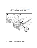
Page 175: ...plane This routing must be duplicated when the backplane unit is reinstalled 2 Remove the three 3 cable connectors on the forward edge of the 60 mm fan backplane FIGURE 10 5 1 3 Loosen the two 2 green captive screws FIGURE 10 5 2 4 Remove the 60 mm fan backplane from the server and place it on the ESD mat FIGURE 10 5 3 and 4 FIGURE 10 5 Removing the 60 mm Fan Backplane ...

Page 176: ...replacing the fan cover installing the 60 mm fan units sliding the server in to the equipment rack and restoring the rack antitilt features to their original position See Section 5 3 2 Replacing the Fan Cover on page 5 10 3 Power the server on This step includes reconnecting power cables verifying the state of the LEDs and turning the keyswitch to the Locked position See Section 4 4 2 Powering the...

Page 177: ...hen drawing out the SPARC Enterprise M4000 M5000 Server to the front release the cable tie holding the PCI cables on the rear of the server 2 Deploy the rack s antitilt features if applicable and slide the server out of the equipment rack See Section 5 1 1 Sliding the Server Out of the Equipment Rack on page 5 2 Caution Use proper ESD grounding techniques when handling components See Section 1 1 S...

Page 178: ...ember 2010 5 Slide the 172 mm fan backplane towards the interior of the server and then upwards to remove the 172 mm fan backplane 6 Place the 172 mm fan backplane upside down on the ESD mat This must be placed upside down to protect the circuits on the underside ...

Page 179: ...Chapter 10 Fan Modules Replacement 10 15 FIGURE 10 6 Removing the M4000 Server 172 mm Fan Backplane ...

Page 180: ...erver into the equipment rack and secure the stabilizer bar See Section 5 1 2 Sliding the Server Into the Equipment Rack on page 5 4 2 Power on the server This step includes reconnecting power cables verifying the LEDs and turning the keyswitch to the Locked position See Section 4 4 2 Powering the Server On Using Software on page 4 13 Note If the Oracle Solaris automatic booting is set use the sen...

Page 181: ...e When drawing out the M4000 M5000 server to the front release the cable tie holding the PCI cables on the rear of the server 2 Deploy the rack s antitilt features if applicable and slide the server out of the equipment rack See Section 5 1 1 Sliding the Server Out of the Equipment Rack on page 5 2 Caution Use proper ESD grounding techniques when handling components See Section 1 1 Safety Precauti...

Page 182: ...ember 2010 5 Slide the 172 mm fan backplane towards the interior of the server and then upwards to remove the 172 mm fan backplane 6 Place the 172 mm fan backplane upside down on the ESD mat This must be placed upside down to protect the circuits on the underside ...

Page 183: ...Chapter 10 Fan Modules Replacement 10 19 FIGURE 10 7 Removing the M5000 Server 172 mm Fan Backplane ...

Page 184: ...the server into the equipment rack and secure the stabilizer bar See Section 5 1 2 Sliding the Server Into the Equipment Rack on page 5 4 2 Power on the server This step includes reconnecting power cables verifying the LEDs and turning the keyswitch to the Locked position See Section 4 4 2 Powering the Server On Using Software on page 4 13 Note If the Oracle Solaris automatic booting is set use th...

Page 185: ...boards and DIMMs The information is organized into the following topics Section 11 1 Memory Board Replacement on page 11 1 Section 11 2 DIMM Replacement on page 11 7 11 1 Memory Board Replacement The memory boards are cold replacement components The entire server must be powered off and the power cords disconnected to replace the memory boards ...

Page 186: ...anual December 2010 FIGURE 11 1 shows the memory board location on the M4000 server FIGURE 11 1 M4000 Server Memory Board Locations Location Number Component 1 Memory board MEMB 0 2 Memory board MEMB 1 3 Memory board MEMB 2 4 Memory board MEMB 3 1 2 3 4 ...

Page 187: ... on the M5000 server FIGURE 11 2 M5000 Server Memory Board Locations Location Number Component 1 Memory board MEMB 0 2 Memory board MEMB 1 3 Memory board MEMB 2 4 Memory board MEMB 3 5 Memory board MEMB 4 6 Memory board MEMB 5 7 Memory board MEMB 6 8 Memory board MEMB 7 8 1 2 3 4 5 6 7 ...

Page 188: ...ng Software on page 4 12 Caution To prevent the equipment rack from tipping over you must deploy the antitilt feature if applicable before you slide the server out of the equipment rack Note When drawing out the SPARC Enterprise M4000 M5000 Server to the front release the cable tie holding the PCI cables on the rear of the server 2 Remove the top cover This step includes deploying the rack s antit...

Page 189: ...s simultaneously to unseat the memory board Note Keep track of the original Memory Board locations so that the boards can be returned to the same locations 2 Slide the memory board out of the server and place it on the ESD mat Caution Do not stack more than four memory boards on top of one another FIGURE 11 3 Memory Board Removal ...

Page 190: ... rack and restoring the rack antitilt features to their original position See Section 5 2 2 Replacing the Top Cover on page 5 8 2 Power on the server This step includes reconnecting power cables verifying the state of the LEDs and turning the keyswitch to the Locked position See Section 4 4 2 Powering the Server On Using Software on page 4 13 Note If the Oracle Solaris automatic booting is set use...

Page 191: ...ff and the power cords disconnected to replace the DIMMS FIGURE 11 4 shows the memory board memory slot locations FIGURE 11 4 Memory Board DIMM Slot Numbering Location Number Component 1 MEM 2A Memory Slot Group A 2 MEM 2B Memory Slot Group B 3 MEM 3A Memory Slot Group A 4 MEM 3B Memory Slot Group B 5 MEM 1B Memory Slot Group B 1 2 3 4 5 6 7 8 ...

Page 192: ...lot Group A 7 MEM 0B Memory Slot Group B 8 MEM 0A Memory Slot Group A EXAMPLE 11 1 showhardconf XSCF showhardconf MBU_B Status Normal Ver 0101h Serial 78670002978 FRU Part Number CF00541 0478 01 541 0478 01 Memory_Size 64 GB MEM 0A Status Normal Code c1000000000000004572T128000HR3 7A 252b 04123520 Type 1B Size 1 GB MEM 0B Status Normal Code c1000000000000004572T128000HR3 7A 252b 04123e25 Type 1B S...

Page 193: ...group A must be equal to or larger than the size of the DIMMs in group B You need not necessarily mount DIMMs in group B In each of the groups mount the DIMM of same size and of same rank The DIMMs of different size cannot be mixed in a group To replace with the DIMMs of different size or different rank you need to follow the above conditions on every memory board in the same CMU Note When you upg...

Page 194: ...ition confirming that the POWER LED is off and disconnecting power cables See Section 4 4 1 Powering the Server Off Using Software on page 4 12 Caution To prevent the equipment rack from tipping over you must deploy the antitilt feature if applicable before you slide the server out of the equipment rack Note When drawing out the SPARC Enterprise M4000 M5000 Server to the front release the cable ti...

Page 195: ...moving the DIMMs 1 Open the plastic hinged DIMM cover on the memory board cover to expose the DIMMs 2 Pull the DIMM eject levers outwards to release the DIMM 3 Pull the DIMM upwards to remove the DIMM from the socket FIGURE 11 6 FIGURE 11 6 DIMM Removal ...

Page 196: ... to their original position See Section 5 2 2 Replacing the Top Cover on page 5 8 3 Power on the server This step includes reconnecting power cables verifying the state of the LEDs and turning the keyswitch to the Locked position See Section 4 4 2 Powering the Server On Using Software on page 4 13 Note If the Oracle Solaris automatic booting is set use the sendbreak d domain_id command after the d...

Page 197: ...to the following topis Section 12 1 CPU Module Replacement on page 12 1 Section 12 2 CPU Upgrade on page 12 7 12 1 CPU Module Replacement The CPU modules are cold replacement components The entire server must be powered off and the power cords disconnected to replace the CPU modules The CPU modules on the midrange servers are identical ...

Page 198: ...4000 M5000 Servers Service Manual December 2010 FIGURE 12 1 shows the CPU module location on the M4000 server FIGURE 12 1 M4000 Server CPU Module Locations Location Number Component 1 CPU module CPUM 1 2 CPU module CPUM 0 2 1 ...

Page 199: ...ment 12 3 FIGURE 12 2 shows the CPU module location on the M5000 server FIGURE 12 2 M5000 Server CPU Module Locations Location Number Component 1 CPU module CPUM 0 2 CPU module CPUM 1 3 CPU module CPUM 2 4 CPU module CPUM 3 1 2 3 4 ...

Page 200: ...g Software on page 4 12 Caution To prevent the equipment rack from tipping over you must deploy the antitilt feature if applicable before you slide the server out of the equipment rack Note When drawing out the SPARC Enterprise M4000 M5000 Server to the front release the cable tie holding the PCI cables on the rear of the server 2 Remove the top cover This step includes deploying the rack s antiti...

Page 201: ...multaneously to unseat the CPU module FIGURE 12 3 Caution The bottom of the board tends to swing when it is removed 2 Remove the CPU module or filler panel from the server and place it on the ESD mat FIGURE 12 3 CPU Module Removal Caution Do not stack CPU modules on top of one another or on top of other components ...

Page 202: ...2 2 Replacing the Top Cover on page 5 8 2 Power on the server This step includes reconnecting power cables verifying the state of the LEDs and turning the keyswitch to the Locked position See Section 4 4 2 Powering the Server On Using Software on page 4 13 Note If the Oracle Solaris automatic booting is set use the sendbreak d domain_id command after the display console banner is displayed but bef...

Page 203: ...ris OS will vary based on the processor type For details see the latest version of the Product Notes for XCP version 1100 or later for your server Caution You must complete the upgrades to the XCP firmware and to Oracle Solaris OS before inserting SPARC64 VII SPARC64 VII processors into the chassis For more information about configuring combinations of processors in domains refer to Section 2 2 13...

Page 204: ...omains have stopped 5 Change the key position on the operator panel from Locked to Service 6 Collect an XSCF snapshot to archive system status prior to upgrade If a problem should occur during the upgrade procedure a snapshot of the system status might be helpful 7 Update the XCP version For instructions for updating the firmware refer to the SPARC Enterprise M3000 M4000 M5000 M8000 M9000 Servers ...

Page 205: ...stalled CPU module is recognized by the server and that the error indicator asterisk is not displayed 12 Confirm that no error has occurred 13 Change the key position on the operator panel from Service to Locked 14 Power on the existing domains 15 Set the following for the added CPU module Set up XSB for the added CPU module Set up the domain XSCF testsb 01 XSCF testsb 01 Initial diagnosis is abou...

Page 206: ... no error has occurred 20 Install a version of the Oracle Solaris OS that supports SPARC64 VII SPARC64 VII processors Note Supported firmware and Oracle Solaris OS will vary based on the processor type For details see the latest version of the Product Notes for XCP version 1100 or later for your server For information about network based installations refer to Solaris 10 8 07 Installation Guide Ne...

Page 207: ... to SPARC64 VII SPARC64 VII on an Existing Domain on page 12 15 Preparing to Add SPARC64 VII SPARC64 VII Processors to an Existing Domain 1 If necessary upgrade to a version of Oracle Solaris OS that supports SPARC64 VII SPARC64 VII processors Note Supported firmware and Oracle Solaris OS will vary based on the processor type For details see the latest version of the Product Notes for XCP version ...

Page 208: ...o start the Oracle Solaris OS 11 Check the updated OpenBoot PROM version The following example shows output for XCP 1081 in which the version of OpenBoot PROM is 02 08 0000 12 Turn off the power to all the domains XSCF snapshot t user host directory XSCF poweron a XSCF version c cmu v XSCF version c cmu v DomainID 0 02 08 0000 DomainID 1 02 08 0000 DomainID 2 02 08 0000 DomainID 3 02 08 0000 XSB 0...

Page 209: ...re must be preceded by Preparing to Add SPARC64 VII SPARC64 VII Processors to an Existing Domain on page 12 11 If you have not completed that procedure do so before continuing 1 Install the CPUM in the server For instructions refer to the CPU Module Replacement chapter in the SPARC Enterprise M4000 M5000 Servers Service Manual Note that this procedure involves powering down the entire server Cauti...

Page 210: ... for the CPU module Set up XSB Set up the LSB Add the XSB to the domain Set up the CPU operational mode on the domain Refer to Chapter 2 Setting Up XSCF in the SPARC Enterprise M3000 M4000 M5000 M8000 M9000 Servers XSCF User s Guide for information about these settings 7 Power on all the domains 8 Confirm that all the domains have been correctly started 9 Confirm that no error has occurred XSCF sh...

Page 211: ...anual Note that this procedure involves powering down the entire server Caution After installing the CPU module you must reconnect the power cable to the power supply 2 Log in to the XSCF again using an account with platadm or fieldeng privileges 3 Perform an initial diagnosis of the newly installed CPU module The following example shows a test after adding PSB 01 to a SPARC Enterprise M5000 serve...

Page 212: ...CPU operational mode of the domain For more information refer to Chapter 2 Setting Up XSCF in the SPARC Enterprise M3000 M4000 M5000 M8000 M9000 Servers XSCF User s Guide 8 Power on all the domains 9 Confirm that the target domain has been correctly started 10 Confirm that no error has occurred XSCF showlogs error v XSCF showstatus XSCF poweron a XSCF showlogs power XSCF showlogs error v XSCF show...

Page 213: ...Section 13 1 Motherboard Unit Replacement on page 13 1 Section 13 2 DC DC Converter Replacement on page 13 12 Section 13 3 Motherboard Unit Upgrade on page 13 19 13 1 Motherboard Unit Replacement The motherboard unit MBU is a cold replacement component This means the entire server must be powered off and the power cords disconnected to replace the motherboard unit ...

Page 214: ...13 2 SPARC Enterprise M4000 M5000 Servers Service Manual December 2010 FIGURE 13 1 shows the location of the motherboard unit on the M4000 server FIGURE 13 1 M4000 Server Motherboard Unit Location ...

Page 215: ...Chapter 13 Motherboard Unit Replacement 13 3 FIGURE 13 2 shows the location of the motherboard unit on the M5000 server FIGURE 13 2 M5000 Server Motherboard Unit Location ...

Page 216: ...ront release the cable tie holding the PCI cables on the rear of the server 2 Remove the top cover This step includes deploying the rack s antitilt features if applicable sliding the server out of the equipment rack and removing the top cover See Section 5 2 1 Removing the Top Cover on page 5 5 Caution Use proper ESD grounding techniques when handling components See Section 1 1 Safety Precautions ...

Page 217: ...g the M4000 Server Motherboard Unit 1 Push the server back into the rack 2 Loosen the two captive screws that secure the motherboard unit handle in place 3 Pull the motherboard unit handle down FIGURE 13 3 FIGURE 13 3 Removing the M4000 Server Motherboard Unit ...

Page 218: ...ws to secure the motherboard unit handle 4 Pull the system out of the rack 13 1 4 Securing the Server 1 Install all CPU modules and filler panels See Section 12 1 3 Installing the CPU Module on page 12 6 2 Install all memory boards See Section 11 1 3 Installing the Memory Board on page 11 6 3 Install the top cover This step includes sliding the server in to the equipment rack and restoring the ant...

Page 219: ...s step includes turning the key switch to the Service position confirming that the POWER LED is off and disconnecting power cables See Section 4 4 1 Powering the Server Off Using Software on page 4 12 Caution To prevent the equipment rack from tipping over you must deploy the antitilt feature if applicable before you slide the server out of the equipment rack Note When drawing out the M4000 M5000 ...

Page 220: ...se the latch and pull the two 2 CPU module baffles out of the server FIGURE 13 4 2 Remove the eight 8 bus bar screws at the front of the server using a magnetic screwdriver 3 Loosen the two 2 captive screws in the center of the motherboard unit to release the motherboard unit handles 4 Pull the motherboard unit handles until they are vertical This unseats the motherboard unit from the backplane Ca...

Page 221: ...Chapter 13 Motherboard Unit Replacement 13 9 FIGURE 13 4 Removing the M5000 Server Motherboard Unit ...

Page 222: ...ety Precautions on page 1 1 1 Align the motherboard unit feet with the rails and lower the unit into the server 2 Push the motherboard unit handles down until they are horizontal to seat the board 3 Tighten the two 2 captive screws in the center of the motherboard unit to secure the motherboard unit handles in place 4 Secure the eight 8 bus bar screws at the front of the motherboard unit using a m...

Page 223: ...5 8 4 Power on the server This step includes reconnecting power cables verifying the state of the LEDs and turning the keyswitch to the Locked position See Section 4 4 2 Powering the Server On Using Software on page 4 13 Note If the Oracle Solaris automatic booting is set use the sendbreak d domain_id command after the display console banner is displayed but before the system starts booting the op...

Page 224: ...is means the entire server must be powered off and the power cords disconnected to replace a DC DC converter FIGURE 13 5 shows the location of the DC DC converter on the M4000 server FIGURE 13 5 M4000 Server DC DC Converter Location Location Number Component 1 DC DC Converter DDC_B 0 with metal heatsink 2 DC DC Converter DDC_A 0 3 DC DC Converter DDC_A 1 1 2 3 ...

Page 225: ...n the M5000 server FIGURE 13 6 M5000 Server DC DC converter Location Location Number Component 1 DC DC Converter DDC_A 0 2 DC DC Converter DDC_A 1 3 DC DC Converter DDC_A 2 4 DC DC Converter DDC_A 3 5 DC DC Converter DDC_B 0 with metal heatsink 6 DC DC Converter DDC_B 1 with metal heatsink 1 2 3 5 6 4 ...

Page 226: ...quipment rack from tipping over you must deploy the antitilt feature if applicable before you slide the server out of the equipment rack Note When drawing out the M4000 M5000 Server to the front release the cable tie holding the PCI cables on the rear of the server 2 Remove the top cover This step includes deploying the rack s antitilt features if applicable sliding the server out of the equipment...

Page 227: ... 13 Motherboard Unit Replacement 13 15 13 2 2 Removing the M4000 Server DC DC Converter Pull the DC DC converter from the socket and place it on the ESD mat FIGURE 13 7 FIGURE 13 7 Removing the DC DC Converter ...

Page 228: ...es sliding the server in to the equipment rack and restoring the antitilt features to their original position See Section 5 2 2 Replacing the Top Cover on page 5 8 3 Power on the server This step includes reconnecting power cables verifying the state of the LEDs and turning the keyswitch to the Locked position See Section 4 4 2 Powering the Server On Using Software on page 4 13 Note If the Oracle ...

Page 229: ... from tipping over you must deploy the antitilt feature if applicable before you slide the server out of the equipment rack Note When drawing out the M4000 M5000 Server to the front release the cable tie holding the PCI cables on the rear of the server 2 Remove the top cover This step includes deploying the rack s antitilt features if applicable sliding the server out of the equipment rack and rem...

Page 230: ...nverters without heatsinks are installed in these slots serious system damage may result 1 Place the DC DC converter in the open slot 2 Push gently downward to seat the DC DC converter in the slot 13 2 8 Securing the Server 1 Install all memory boards See Section 11 1 3 Installing the Memory Board on page 11 6 2 Install the top cover This step includes sliding the server in to the equipment rack a...

Page 231: ...ion 13 3 1 Notes on Upgrading on page 13 19 Section 13 3 2 Replacing a Motherboard Unit as an Upgrade in an Existing Domain on page 13 20 13 3 1 Notes on Upgrading Supported firmware and software For new upgrades ensure that you have the minimum supported XCP firmware and Oracle Solaris software version For the SPARC64 VII SPARC64 VII processor the XCP version to be used varies by the CPU operatin...

Page 232: ... with new MBU apply the appropriate patches to the software in use if necessary 3 Log in to XSCF using an account with the platadm privilege 4 Use the showstatus 8 command to confirm that a component in Faulted or Deconfigured status does not exist If there is no problem the message of No failures found in System Initialization appears If case of other messages contact a certified service engineer...

Page 233: ...is of the newly installed MBU The following example shows a test after adding PSB 01 to a SPARC Enterprise M5000 server 13 Confirm that the replaced component has been recognized by the server and the error indicator asterisk is not displayed 14 Use the showlogs error v command and the showstatus 8 command to confirm that no errors occurred 15 Change the mode switch setting on the operator panel f...

Page 234: ...8 Confirm that the target domain has been properly started 19 Use the showlogs error v command and the showstatus 8 command to confirm that no errors occurred If you found any errors on the hardware contact a certified service engineer XSCF poweron a XSCF showlogs power XSCF showlogs error v XSCF showstatus ...

Page 235: ...backplane unit requires shutting the server down entirely and removing the I O units power supplies and the motherboard This chapter contains the following topic Section 14 1 Backplane Unit Replacement on page 14 1 14 1 Backplane Unit Replacement The backplane unit is a cold replacement component This means the entire server must be powered off and the power cords disconnected to replace the backp...

Page 236: ...14 2 SPARC Enterprise M4000 M5000 Servers Service Manual December 2010 FIGURE 14 1 shows the backplane unit location on the M4000 server FIGURE 14 1 M4000 Server Backplane Unit Location ...

Page 237: ...kplane Unit Caution There is an electrical hazard if the power cords are not disconnected All power cords must be disconnected to completely remove power from the server 1 Power off the server This step includes turning the key switch to the Service position confirming that the POWER LED is off and disconnecting power cables See Section 4 4 1 Powering the Server Off Using Software on page 4 12 ...

Page 238: ...e XSCF Unit on page 9 4 Caution To prevent the equipment rack from tipping over you must deploy the antitilt feature if applicable before you slide the server out of the equipment rack Note When drawing out the M4000 M5000 server to the front release the cable tie holding the PCI cables on the rear of the server 4 Remove the top cover This step includes deploying the rack s antitilt features if ap...

Page 239: ... removed 8 Remove the CD RW DVD RW Drive Backplane This step includes removing the CD RW DVD RW Drive Unit and the CD RW DVD RW Drive Backplane See Section 6 2 7 Removing the CD RW DVD RW Drive Backplane of the M4000 Server on page 6 18 9 Remove the 60 mm fan backplane This step includes removing the cable connectors loosening the captive screws and removing the 60 mm fan backplane See Section 10 ...

Page 240: ...ets have flaps that close for thermal reasons If the flaps trap your hand lift your hand upwards rather than outwards to free it 3 Remove the backplane unit a Angle the backplane unit and then pull it partially out of the server b Reach one hand through the power supply opening and disconnect the grey operator panel cable from the backplane unit c Remove the backplane unit and place it on an ESD m...

Page 241: ...s in the plastic cable router One bundle of multicolored cables does not fit in the router all other cables should fit You must pay particular attention to the long blue serial cable that need to reach to the tape backplane 5 Reconnect the backplane end of the ground cable 6 Install the 60 mm fan backplane This step includes installing the 60 mm fan backplane tightening the captive screws and secu...

Page 242: ...unit 3 Install the motherboard unit This step includes installing the CPU modules and reattaching the cable management arm See Section 13 1 3 Installing the M4000 Server Motherboard Unit on page 13 6 4 Install the XSCF unit See Section 9 1 3 Installing the XSCF Unit on page 9 5 5 Install the I O unit See Section 8 3 3 Installing the I O Unit on page 8 11 6 Install the power supply units See Sectio...

Page 243: ...ep includes turning the key switch to the Service position confirming that the POWER LED is off and disconnecting power cables See Section 4 4 1 Powering the Server Off Using Software on page 4 12 Caution To prevent the equipment rack from tipping over you must deploy the antitilt feature if applicable before you slide the server out of the equipment rack Note When drawing out the M4000 M5000 serv...

Page 244: ...ptive screws on the motherboard unit handle and removing the motherboard See Section 13 1 6 Removing the M5000 Server Motherboard Unit on page 13 8 14 1 6 Removing the M5000 Server Backplane Unit 1 Unscrew and disconnect the red cable from the backplane unit 2 Unscrew and disconnect the white cable from the backplane unit 3 Disconnect the two 2 blue serial cables from the backplane unit 4 Disconne...

Page 245: ...Chapter 14 Backplane Unit Replacement 14 11 FIGURE 14 4 Removing the M5000 Server Backplane ...

Page 246: ...plane power cable to the backplane unit 7 Tighten the screws that secure the red cable to the busbar to the left 8 Tighten the screws that secure the white cable to the busbar to the right 14 1 8 Securing the Server Caution The motherboard is heavy Two people are recommended to lift the unit 1 Install the motherboard unit This step includes installing the mother board cradle tightening the captive...

Page 247: ...rning the keyswitch to the Locked position See Section 4 4 2 Powering the Server On Using Software on page 4 13 Note If the Oracle Solaris automatic booting is set use the sendbreak d domain_id command after the display console banner is displayed but before the system starts booting the operating system to get the ok prompt 7 Confirm the hardware This step includes running programs to be certain ...

Page 248: ...14 14 SPARC Enterprise M4000 M5000 Servers Service Manual December 2010 ...

Page 249: ... 15 4 15 1 Operator Panel Replacement The operator panel is a cold replacement component This means the entire server must be powered off and the power cords disconnected to replace the operator panel Note If you replace the XSCF unit and the operator panel simultaneously system will not operate normally Execute the showhardconf command or the showstatus command to confirm that the component repla...

Page 250: ...ise M4000 M5000 Servers Service Manual December 2010 FIGURE 15 1 shows the location of the operator panel on the M4000 server FIGURE 15 1 M4000 Server Operator Panel Locations Location Number Component 1 Operator panel 1 ...

Page 251: ...ter 15 Operator Panel Replacement 15 3 FIGURE 15 2 shows the location of the operator panel on the M5000 server FIGURE 15 2 M5000 Server Operator Panel Locations Location Number Component 1 Operator panel 1 ...

Page 252: ...ion To prevent the equipment rack from tipping over you must deploy the antitilt feature if applicable before you slide the server out of the equipment rack Note When drawing out the M4000 M5000 server to the front release the cable tie holding the PCI cables on the rear of the server 2 Deploy the rack s antitilt features if applicable and slide the server out of the equipment rack See Section 5 1...

Page 253: ...witch cable FIGURE 15 3 2 Press the small tab and disconnect the operator panel signal cable 3 Loosen the captive screw that holds the operator panel in place 4 From the front push the operator panel towards the interior of the server 5 Remove the operator panel from the guide pins and place it on the ESD mat ...

Page 254: ...15 6 SPARC Enterprise M4000 M5000 Servers Service Manual December 2010 FIGURE 15 3 Removing the Operator Panel ...

Page 255: ...gnal cable 15 2 3 Securing the Server 1 Slide the server into the equipment rack and secure the stabilizer bar See Section 5 1 2 Sliding the Server Into the Equipment Rack on page 5 4 2 Install the fan cage and tighten the three 3 captive screws to secure it in place The SPARC Enterprise M4000 server uses only two 2 captive screws 3 Install the 172 mm fan units See Section 10 1 7 Installing the 17...

Page 256: ...15 8 SPARC Enterprise M4000 M5000 Servers Service Manual December 2010 ...

Page 257: ...A 1 APPENDIX A Components List This appendix shows the server nomenclature and component numbering FIGURE A 1 shows the M4000 server ...

Page 258: ...mm fan FAN_B 1 23 DC DC Converter DDC_A 1 3 Top cover 24 Motherboard unit MBU_A 4 Fan cover 25 Motherboard carriage 5 Backplane unit BPU_A includes IOBP Power distribution board 26 CPU module CPUM 1 6 172 mm fan backplane FANBP_A 27 CPU module CPUM 0 7 60 mm fan backplane FANBP_B 28 Memory board MEMB 3 1 2 5 11 13 14 17 16 18 20 37 35 36 28 27 26 21 12 19 29 30 31 35 34 33 32 4 15 7 8 9 10 3 6 22 ...

Page 259: ...drive HDD 0 34 PCI cassette IOU 0 PCI 2 14 Tape drive unit TAPEU 35 PCI cassette IOU 0 PCI 3 15 Front panel 36 PCI cassette IOU 0 PCI 4 16 Power supply unit 48V PSU 0 37 eXtended System Control facility unit XSCFU 17 Power supply unit 48V PSU 1 38 I O unit IOU 0 18 Operator panel OPNL 39 DC DC Converter Riser DDCR IOU 0 Not shown 19 172 mm fan module FAN_A 0 40 DC DC Converter DDC_B on DDCR on IOU...

Page 260: ...vice Manual December 2010 FIGURE A 2 M5000 Server Component Locations 1 54 17 19 46 2 3 4 5 6 8 7 9 10 16 18 20 21 22 23 24 25 26 41 42 43 45 44 36 37 39 38 40 27 55 56 57 58 59 60 62 61 11 12 13 14 15 47 48 49 50 51 52 53 29 28 30 31 32 33 34 35 ...

Page 261: ... 42 PCI cassette PCI 3 IOU 0 12 CD RW DVD RW backplane DVDBP_B 43 PCI cassette PCI 2 IOU 0 13 Tape backplane TAPEBP 44 PCI cassette PCI 1 IOU 0 14 Hard disk drive backplane HDDBP 1 IOU 1 45 PCI cassette PCI 0 IOU 0 15 Hard disk drive backplane HDDBP 0 IOU 0 46 Extended System Control facility unit XSCFU 16 Hard disk drive HDD 1 IOU 0 47 DC DC Converter DDC_A 0 17 Hard disk drive HDD 0 IOU 0 48 DC ...

Page 262: ... MEMB 4 28 I O unit IOU 0 59 Memory Board MEMB 3 29 DC DC Converter Riser DDCR IOU 0 Not shown 60 Memory board MEMB 2 30 DC DC Converter DDC_B on DDCR on IOU 0 Not shown 61 Memory board MEMB 1 31 DC DC Converter DDC_A 0 IOU 0 Not shown 62 Memory board MEMB 0 Location Number Component Location Number Component ...

Page 263: ... APPENDIX B Rules for System Configuration This appendix shows the system configurations for the midrange servers B 1 Server Configuration TABLE B 1 shows the hardware configuration of the midrange servers ...

Page 264: ...PU module 2 4 The CPU module consists of two CPU chips The CPU is a high performance multicore processor It contains an on chip secondary cache to minimize memory latency It supports the instruction retry function that enables continuous processing by retrying instructions when any error is detected At least one CPU Module CPUM is required on each XSB Memory board 8 DIMMs per memory board 4 32 DIM...

Page 265: ...d XSB the slots on an IOU are divided up among the first two parts of a quad XSB The assignments cannot be changed A separate CPUM and MEMB are required on each part of the quad XSB in order to access the slots of the IOU assigned to the parts of the quad XSB PCI cassettes 5 cassettes per tray in the IOU 5 cassettes per tray in the IOU 2 IOUs 10 cassettes PCI cards 5 1 PCI X and 4 PCIe 10 2 PCI X ...

Page 266: ...Four fans per server Two 172 mm fans One fan is redundant Two 60 mm fans One fan is redundant Four 172 mm fans per server Two fans are redundant Internal drives 1 DVDU 2 hard disk drives 1 tape drive unit optional 1 DVDU 4 hard disk drives 1 tape drive unit optional TABLE B 1 System Features Continued Features M4000 Server M5000 Server Notes ...

Page 267: ... 7 Section C 6 FAN Module on page C 8 Section C 7 eXtended System Control Facility Unit on page C 9 Section C 8 Drives on page C 10 C 1 Server Overview The SPARC Enterprise M4000 M5000 servers from Oracle and Fujitsu are high performance systems based on the SPARC 64 VI or SPARC 64 VII SPARC 64 VII processors that use the Oracle Solaris Operating System They share common field replaceable units FR...

Page 268: ...d For details see the relevant software manuals TABLE C 1 Midrange Server FRU Components Component Redundant Cold Replacement Hot Replacement Active Replacement Motherboard unit No Yes Motherboard DC DC Converter No Yes CPU module No Yes Memory board Yes Yes DIMM No Yes eXtended System Control facility unit No Yes I O unit No Yes I O DC DC Converter No Yes I O DC DC Converter Riser No Yes PCI cass...

Page 269: ...gh the busbar I O backplane power backplane unit Motherboard DC DC Converter The M4000 server motherboard unit provides power and signals to its mounted components by a riser card The M5000 server motherboard unit supplies power to its mounted components from the power supply backplane by the bus bar I O backplane power backplane unit To remove and replace the motherboard you must power off the sy...

Page 270: ...ocessors per CPU module with four CPU modules there are eight processors and 32 cores SPARC Instruction Set Architecture ISA Visual Instruction Set VIS extension which accelerates multimedia networking encryption and Java processing Refer to Section 12 1 CPU Module Replacement on page 12 1 for replacement procedures TABLE C 2 CPU Module Features M4000 Server SPARC64 VI M4000 Server SPARC64 VII SPA...

Page 271: ...ase The servers use double data rate DDR II type memory with the following features ECC error protection Recovery from memory chip failures Mirror configuration Refer to Section 11 1 Memory Board Replacement on page 11 1 for replacement procedures TABLE C 3 Memory Board Features M4000 Server M5000 Server Maximum Number of memory boards 4 8 Maximum Number of DIMMs 32 8 DIMMs per memory board 64 8 D...

Page 272: ...nterface cards in the system The I O unit IOU is identical in both midrange servers The IOU monitors I O events and has the following features PCI cards see TABLE C 4 Inter integrated circuit I2C components for environmental monitoring PCI Express switches or bridges connected to the slots There is one IOU in the SPARC Enterprise M4000 server and two IOUs in the SPARC Enterprise M5000 server Each ...

Page 273: ... protocols and a faster clock rate compared with the parallel bus PCI standard TABLE C 5 Power Supply Features M4000 Server M5000 Server Number of power cords 1 power cord per power supply unit 2 power cords are required for redundancy 1 power cord per power supply unit 4 power cords are required for redundancy Redundancy 1 1 redundant Second power supply is redundant at 200 VAC 2 2 redundant Seco...

Page 274: ... currents into and out of the server If one fan fails the eXtended System Control Facility XSCF detects the failure and uses the redundant fan s Both servers use 172 mm fans FAN_A as the primary cooling system The 60 mm fans FAN_B in the M4000 server are used for additional cooling TABLE C 6 describes the fan features Volt ampere 1 763 VA 3 406 VA Power draw maximum 1 692W 2 power cords 3 270W 4 p...

Page 275: ... Solaris OS power on self test POST and the OpenBoot PROM Controls and manages the interface for the system administrator such as a terminal console Administers device information Messages various events remotely Interlocks power due to remote cabinet interface RCI Note To use RCI a SPARC Enterprise server or a device with an RCI port is required Both midrange servers have one XSCF unit which is s...

Page 276: ... Section 6 1 Hard Disk Drive Replacement on page 6 1 for replacement procedures TABLE C 7 Drives Offered on the Midrange Servers M4000 Server M5000 Server 2 hard disk drives 4 hard disk drives 1 CD RW DVD RW Drive Unit 1 CD RW DVD RW Drive Unit 1 tape drive unit optional Contact your sales representative for tape drive unit options on M4000 M5000 servers 1 tape drive unit optional TABLE C 8 Hard D...

Page 277: ... TABLE C 9 CD RW DVD RW Drive Unit Features and Specifications for Midrange Servers Midrange Servers Number of CD RW DVD RW Drive Units 1 Location Front of system to the right of the disk drives Active replacement capability No Hot replacement capability Yes Cold replacement capability Yes Interface Advanced Technology Attachment Packet Interface ATAPI TABLE C 10 Tape Drive Unit Features and Speci...

Page 278: ...ata noncompressed format 72 Gbytes of data double compressed format Media type Sequential access Contact your sales representative for tape drive unit options on M4000 M5000 servers TABLE C 11 Serial Advanced Technology Attachment SATA Specifications Transfer Rate 150 MB per second or faster see TABLE C 10 Cable length Up to one meter 39 37 inches Design Advantage Thinner than conventional serial ...

Page 279: ...describes the specifications of the connectors provided on the SPARC Enterprise server unit Section D 1 Serial Port on page D 2 Section D 2 UPC UPS Control Port on page D 3 Section D 3 USB Port on page D 3 Section D 4 Connection Diagram for Serial Cable on page D 4 ...

Page 280: ...Port TABLE D 1 Serial Port Setting Pin No Signal Name Input Output Description 1 RTS Output Request to Send 2 DTR Output Data Terminal Ready 3 TXD Output Send Data 4 GND Ground 5 GND Ground 6 RXD Input Receive Data 7 DSR Input Data Set Ready 8 CTS Input Clear to Send 12 4 6 8 3 5 7 ...

Page 281: ...nal 2 NC Not connected 3 NC Not connected 4 NC Not connected 5 SG Ground 6 BPS Input UPS hardware error signal 7 BTL Input Battery end of discharge warning signal 8 NC Not connected 9 ACOFF Input Power failure detection signal TABLE D 3 USB Port Setting Pin No Signal Name Input Output Description 1 VBUS Output Power supply 2 DATA Input output Data 3 DATA Input output Data 4 GND Ground 9 8 7 6 5 4 ...

Page 282: ...D 4 SPARC Enterprise M4000 M5000 Servers Service Manual December 2010 D 4 Connection Diagram for Serial Cable FIGURE D 1 Connection Diagram for Serial Cable ...

Page 283: ... A UPS unit is used to provide a stable supply of power to the system in the event of a power failure or an extensive power interruption When a failure is detected in the supply of power an error can be reported to the server through the signal cable connection between a UPC port on the server and a UPS that has the UPC interface Then the server can execute emergency shutdown processing to safely ...

Page 284: ...Line Configuration This section describes signal definitions and electrical specifications FIGURE E 1 shows the signal line configuration when connected to a UPS FIGURE E 1 Connection with UPS TABLE E 1 defines these signal lines UPS cable UPS Server BTL ACOFF SG 7 6 9 5 BPS UALM 1 ...

Page 285: ...Input circuit Limit the signal line chatter period to 1ms or less Signal Name Definitions Pin Number Remarks BPS UALM Signal indicates faulty UPS conditions 6 Normal OFF Failure ON BTL Signal provides a warning of a low battery level and a pending UPS failure 7 Normal OFF Warning ON Note1 ACOFF Signal indicates power failure at the commercial AC supply connector to the UPS 9 Normal OFF Power failu...

Page 286: ... install side Female DEU 9PF F0 Terminal array FIGURE E 2 identifies pin signals of the UPC connector and the UPS cable Do not use the unused pins pin number 2 3 4 and 8 in the following diagram Cable side shown below TABLE E 3 Electrical Specifications Signal Name Output Conditions ER Output Voltage VOH 3 76 VDC min VOL 0 to 0 4 VDC max Output Current IOH 4 mA max IOL 4 mA max ...

Page 287: ...s representatives E 6 UPC Connector This chapter describes the location of the UPC connector and the UPS connections UPC 0 connects with UPS 0 UPC 1 connects with UPS 1 The single power feed uses UPC 0 only The dual power feed option uses UPC 0 and UPC 1 Note Do not use ER signal Note BTL BPS UALM ACOFF SG ER UPC port side UPS cable side BTL BPS UALM ACOFF SG 1 2 3 4 5 6 7 8 9 Pin Signal name ...

Page 288: ...E 6 SPARC Enterprise M4000 M5000 Servers Service Manual December 2010 ...

Page 289: ... filtering is needed This chapter describes how to install remove and service these air filters Section F 1 M4000 and M5000 Servers Air Filter on page F 2 Section F 2 Air Filter Installation for the M4000 Server on page F 3 Section F 3 Air Filter Installation for the M5000 Server on page F 9 FIGURE F 1 M4000 Server with Air Filter Installed ...

Page 290: ...mains off Perform the Command Operations Install the Air Filter Reset the XSCF Power the Domains on F 1 1 Command Operations Procedures Before physically installing the air filters the server must be made ready to deal with the new air flow 1 Login to XSCF 2 Use the showaltitude 8 command to check that the air filter is not currently being mounted 3 Turn off power to all domains 4 Install the air ...

Page 291: ...it the filter to the front bezel of the server to make sure you know where it will attach to the server FIGURE F 1 Clean the surface of the front bezel where the hook and loop tapes make contact Make sure the bezel is clean and dry before proceeding 1 Locate the protective strips on the back side of the filter and clean the bezel in the same places as the tape FIGURE F 2 XSCF showaltitude 1000m Fi...

Page 292: ...F 4 SPARC Enterprise M4000 M5000 Servers Service Manual December 2010 FIGURE F 2 Hook and Loop Tape Locations ...

Page 293: ...Appendix F Air Filters F 5 2 Carefully remove the tape protective backing leaving the hook and loop tape still attached to the filter FIGURE F 3 Removing the Tape Protective Backing ...

Page 294: ...rvice Manual December 2010 3 Carefully position the air filter to the front of the server making sure not to impede the removal of the hard disk drive or CD RW DVD RW drive unit FIGURE F 4 Installing the Air Filter to the SPARC Enterprise M4000 ...

Page 295: ...s firmly at all places where the sticky tape comes in contact with the bezel The air filter is now installed 5 Return to Step 4 of Section F 1 1 Command Operations Procedures on page F 2 FIGURE F 5 Air Filter Installed on M4000 Server ...

Page 296: ...m the M4000 Server This section covers how to remove the air filter for servicing power supplies or servicing the air filter 1 Grasp the top edge corners of the air filter and slowly pull the air filter away and down from the front of the server FIGURE F 6 FIGURE F 6 Removing the M4000 Server Air Filter ...

Page 297: ...ilter to the front bezel of the server to make sure you know where it will attach to the server FIGURE F 1 Clean the surface of the front bezel where the hook and loop tapes make contact Make sure the bezel is clean and dry before proceeding FIGURE F 7 M5000 Server With Air Filters Installed ...

Page 298: ...he same places as the tape 2 Carefully remove the tape protective backing leaving the hook and loop tape still attached to the filter FIGURE F 8 FIGURE F 8 Hook and Loop Tape Locations 3 Carefully position the air filters to the front of the server making sure not to impede the removal of the hard disk drive or CD RW DVD RW drive FIGURE F 9 and FIGURE F 10 ...

Page 299: ...Appendix F Air Filters F 11 FIGURE F 9 Installing the Upper Air Filter to the M5000 Server FIGURE F 10 Installing the Lower Air Filter to the M5000 Server ...

Page 300: ...ecember 2010 4 Press firmly at all places where the sticky tape comes in contact with the bezel The air filter is now installed 5 Return to Step 4 of Section F 1 1 Command Operations Procedures on page F 2 FIGURE F 11 Air Filters Installed on the M5000 Server ...

Page 301: ...s section covers how to remove the air filter for servicing power supplies or servicing the air filter 1 Grasp the top edge corners of the air filter and slowly pull the air filter away and down from the front of the server FIGURE F 12 FIGURE F 12 Removing the M5000 Server Air Filter ...

Page 302: ... currently being mounted 3 Turn off power to all domains 4 Use the setaltitude 8 command to set the air filter uninstallation 5 Use the showaltitude 8 command to check the setting of air filter 6 Use the rebootxscf 8 command to reset XSCF 7 Start the domain 8 Uninstall the air filter Refer to Section F 2 1 Removing the Air Filter From the M4000 Server on page F 8 9 Take the air filter to the clean...

Page 303: ...Appendix F Air Filters F 15 11 Perform Steps 1 through 8 of Section F 1 1 Command Operations Procedures on page F 2 ...

Page 304: ...F 16 SPARC Enterprise M4000 M5000 Servers Service Manual December 2010 ...

Page 305: ...d technology ATAPI AT attachment packet interface BUI Browser based user interface CH Channel CMP Chip multi processor CMT Chip multithreading CB Circuit breaker CLKU Clock control unit CLI Command line interface CMU CH CMU channel CE Correctable error CPU Central processing unit CPUM CPU module DAT Digital audio tape DCL Domain component list DDC DC to DC converter DE Diagnosis engine DID Domain ...

Page 306: ...er interface HDD Hard disk drive HDDBP Hard disk drive backplane I2C bus Inter integrated circuit bus ISA Instruction set architecture IOBP I O backplane IOU I O unit LCD Liquid crystal display LED Light emitting diode LSB Logical system board LSI Large scale integration MAC Media access control address MBC Maintenance bus controller MEMB Memory modules MBU Motherboard unit NTP Network time protoc...

Page 307: ...Serial ATA SCF eXtended System Controller Facility SRAM Static RAM SC System controller TC Throughput computing TOD Time of day UE Uncorrectable error UPC UPS connection interface UPS Uninterruptible Power Supply XCP XCSF control package XIR Externally initiated reset XSB eXtended System board XSCF eXtended System Control Facility XSCFU eXtended System Control facility unit TABLE G 1 Continued Acr...

Page 308: ...G 4 SPARC Enterprise M4000 M5000 Servers Service Manual December 2010 ...

Page 309: ... DC converter motherboard 13 13 DC DC riser 8 21 diagnostic commands 2 21 diagnostics 2 1 2 4 2 14 DIMMS 11 7 DVD drive 6 12 DVD drive backplane 6 18 E electrical specifications E 3 error messages 2 14 eXtended System Control Facility XSCF C 9 eXtended system control facility XSCF Shell 2 4 eXtended system control facility unit XSCFU C 9 external interface serial port D 2 UPC port D 3 USB port D 3...

Page 310: ... replacement method active replacement 4 4 cold replacement 4 12 hot replacement 4 6 S safety precautions 1 1 service loop 5 5 service processor 9 1 signal cables E 1 slide rails 5 1 storage device C 10 DAT tape drive 6 23 C 11 DVD drive 6 12 C 11 hard disk drive 6 1 C 10 symbols 1 2 system boards CPU module C 4 memory board C 5 motherboard unit C 3 system controller facility unit XSCFU 9 1 system...

Reviews: