background image

U41629-J-Z156-2-76

Options Guide

61

11

Converting from the floorstand 
model to the rack model

V

CAUTION!

Observe the safety instructions in the 

chapter “Safety notes” on page 13


et seqq..

Ê

Open the server and remove the front cover as described in the 

chapter 

“Preparation” on page 19

ff.

I

The front cover is no longer required.

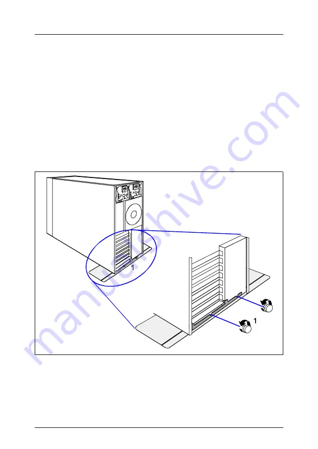
Figure 40: Removing the anti-tilt bracket

Ê

If your server is equipped with an anti-tilt bracket, remove it:

Ê

Remove the two knurled screws (1) and lift the server out of the anti-tilt 
bracket.

Summary of Contents for PRIMERGY TX150 S4

Page 1: ... S4 Server System Options Guide Däschlein Fujitsu Siemens Computers GmbH München 81730 München e mail email manuals fujitsu siemens com Tel 089 61001155 Fax 0 700 372 00000 U41629 J Z156 2 76 Sprachen En Edition February 2006 ...

Page 2: ...according to DIN EN ISO 9001 2000 To ensure a consistently high quality standard and user friendliness this documentation was created to meet the regulations of a quality management system which complies with the requirements of the standard DIN EN ISO 9001 2000 cognitas Gesellschaft für Technik Dokumentation mbH www cognitas de Copyright and Trademarks Copyright 2006 Fujitsu Siemens Computers Gmb...

Page 3: ...ck front cover 25 5 Main memory 27 5 1 Equipping rules 27 5 2 Extending replacing the main memory 28 6 Accessible drives 31 6 1 Installing an accessible 5 25 inch drive 31 6 2 Installing the hard disks extension box 34 6 3 Installing a 3 5 inch floppy disk drive 36 7 Controllers in the PCI slots 39 7 1 Installing a controller 40 7 2 PCI slot assembly 42 8 RemoteView components 43 8 1 RemoteView Se...

Page 4: ...the hard disk cover 67 12 1 2 Attaching the front cover 68 12 1 3 Closing the server 69 12 2 Rack model 70 12 2 1 Attaching the rack front cover 70 12 2 2 Closing the server 72 13 Appendix 75 13 1 Cabling 75 13 1 1 SCSI version 75 13 1 2 SATA version 80 Abbreviations 83 Related publications 89 Index 91 ...

Page 5: ...e online documentation available on the Internet You can go to the PRIMERGY Server documentation by clicking on industry standard servers Concept and target groups This Options Guide shows you how you can expand and upgrade the server I The Operating Manual for the server describes how you install remove the hot plug components The activities described in this manual may only be performed by techn...

Page 6: ...rverStart is also available on the ServerBooks CD I You can order a supplementary ServerBooks CD by sending an e mail to the following address quoting your server data Reklamat PC LOG fujitsu siemens com MegaRAID 320 Storage Adapters PDF file available on the ServerBooks CD MegaRAID 320 0X Zero channel PCI X RAID Storage Adapter PDF file available on the ServerBooks CD MegaRAID Device Driver Insta...

Page 7: ...ry modules with ECC The organization in two memory banks 1 and 2 permits rapid memory access with two way inter leaving If the memory modules are populated in pairs each pair must consist of identical memory modules 2 way interleaved mode Upgrading the processor The LGA775 processor socket Prozessorsteckplatz accomodates one Intel Pentium 4 or Pentium D desktop processor with 533 800 MT s 133 200 ...

Page 8: ... length 1 x 340 mm 2 x 245 mm 1 x PCI Express x1 0 5 GB s length 167 mm 1 x PCI Express x4 2 0 GB s length 167 mm The PCI slot 2 blue is prepared for Zero Channel RAID ZCR RemoteView Service Board S2 LP The RemoteView Service Board S2 LP RSB S2 LP is a PCI board with a completely independent system i e it has its own operating system with Web server and SNMP agents and can optionally be equipped w...

Page 9: ...stand model to a rack model The floorstand model can optionally be converted so that the server can be integrated into the common rack systems 1 3 Notational conventions The following notational conventions are used in this manual Text in italics indicates commands menu items or software programs Quotation marks indicate names of chapters and terms that are being emphasized Ê describes activities ...

Page 10: ......

Page 11: ...manuals see Additional documentation about the server on page 5 are available printing out the PDF files if necessary You will definitely need the Operating Manual for the server and the Technical Manual for the system board Ê Shut down the server correctly switch it off pull out the power plug s and open the server as described in the chapter Preparation on page 19 et seqq Ê Extend or upgrade you...

Page 12: ......

Page 13: ... user to risks electric shock energy hazards fire hazards and could also damage the equipment Please note that any unauthorized openings of the device will result in the invalidation of the warranty and exclusion from all liability Before operating the device V CAUTION During installation and before operating the device observe the instructions on environmental conditions for your device If the de...

Page 14: ...the grounded insulated socket s Always connect the device and the attached peripherals to the same power circuit Otherwise you run the risk of losing data if for example the central processing unit is still running but the peripheral device e g storage subsystem has failed during a power outage Data cables to peripheral devices must be adequately shielded To the LAN wiring the requirements apply i...

Page 15: ...ystem expansions that satisfy the requirements and rules governing safety and electromagnetic compatibility and relating to telecommunications terminal equipment If you install other expan sions you may damage the system or violate the safety regulations and regulations governing RFI suppression Information on which system expansions are suitable can be obtained from the customer service centre or...

Page 16: ...s damage to the device and injuries Therefore check each CD for damage cracks breakage etc before inserting it in the drive Please note that any additional labels applied may change the mechanical properties of a CD and cause imbalance Damaged and imbalanced CDs can break at high drive speeds data loss Under certain conditions sharp edged pieces of broken CDs can penetrate the cover of the drive d...

Page 17: ...e ESD are marked with the following label Figure 1 ESD label When you handle components fitted with ESDs you must observe the following points under all circumstances You must always discharge static build up e g by touching a grounded object before working Use a grounding cable designed for this purpose to connect yourself to the system unit as you install components The equipment and tools you u...

Page 18: ...29 J Z156 2 76 Safety notes Place all components on a static safe base I You will find a detailed description for handling ESD components in the relevant European or international standards DIN EN 61340 5 1 ANSI ESD S20 20 ...

Page 19: ...s and shut down the server correctly Ê If your operating system has not switched off the sever press the on off switch Ê Pull all power connectors out of the power outlets Ê If required remove the lock on the side cover Figure 2 Loosening the screws Ê Unlock the server 1 Ê Loosen the two screws at the rear side 2 Ê Push back the left hand side cover approxiate 2 cm 3 Ê Remove the left hand side co...

Page 20: ...le drives Upgrading the floorstand model to a rack model Ê Remove the hard disk cover as shown in figure 5 on page 21 Figure 3 Removing the front cover Ê Disengage the three tabs 1 on the left side one after the other and rotate the front cover outward 2 about 2 cm Figure 4 Removing the front cover Ê Press the two hooks 1 on the right side inward and pull out the front cover frontward 2 1 2 2 1 ...

Page 21: ...nstalling further hard disk drives Ê Terminate all applications and shut down the server correctly Ê If your operating system has not switched off the sever press the on off switch Figure 5 Removing the hard disk cover Ê Unlock the server 1 and remove the key Ê Push the drive cover up as far as possible 2 Ê Remove the hard disk cover 3 4 1 2 4 3 ...

Page 22: ...the server correctly Ê If your operating system has not switched off the server press the on off button Ê Pull all power connectors out of the power outlets 4 2 1 Opening the server Figure 6 Loosening the knurled screws Ê Loosen the four knurled screws 1 and pull the server as far as possible out of the rack 2 2 1 2 1 ...

Page 23: ...either side of the server 1 Ê Release the locking mechanism 2a 2b of both rails and carefully pull the server out of the rack 3 as far as it will go Ê Pull the server a little in the direction marked 4a until the noses 4b disen ngage V CAUTION At least two people are needed to lift the server out of the rack cabinet Ê Lift the server out of the rails 5 and place it on a table for example 4a 3 2a 2...

Page 24: ...9 J Z156 2 76 Rack model Preparation Figure 8 Loosening the screws Ê Unlock the top cover by removing the two screws on the server rear 1 Ê Push the top cover approxiately 2 cm to the rear 2 Ê Remove the top cover 3 2 3 1 2 ...

Page 25: ... rack front cover Ê Remove two screws on either side 1 Ê Remove the rack front cover to the front 2 Figure 10 Removing the plastic front cover Ê Disengage the three latches 1 on the top side one after the other and pull out the plastic front cover approximately 2 cm 2 Ê Press the two hooks 3 on the bottom side carefully pull out on the plastic front cover and remove it to the front 4 1 1 2 1 3 2 4...

Page 26: ......

Page 27: ...12 Mbyte 1 Gbyte or 2 Gbyte unbuffered DDR 2 memory modules 5 1 Equipping rules Figure 11 Structure of the main memory in memory banks and memory modules Each memory bank is equipped with two memory modules with the same capacity Memory access takes place in 2 way interleaved mode The memory module capacity can differ for the various memory banks e g memory bank 2A 2B can be equipped with two 512 ...

Page 28: ...bed in the chapter Preparation on page 19 et seqq Figure 12 Removing a memory module Ê Flip outwards the ejector tabs on each side of the desired slot 1 Ê If the mounting location has already been equipped carefully remove the memory module from its mounting location 2 DIMM 1A DIMM 2A DIMM 1B DIMM 2B single channel equipped empty empty empty empty equipped empty empty empty empty equipped empty em...

Page 29: ...e Ê Flip outwards the ejector tabs on each side of the desired slot 1 Ê Carefully press the memory module into the DIMM slot until the ejector tabs engage on both sides of the memory module 2 Ê Close the server connect it to the power outlet and switch it on as described in the chapter Completion on page 67 et seqq 2 2 ...

Page 30: ......

Page 31: ...netic tape drives CD DVD ROM drives and CD DVD ROM burners These drives can be installed in the two free 5 25 inch bays Ê Open the server and remove the front cover or rack front cover as described in the chapter Preparation on page 19 et seqq I New 5 25 inch drives are supplied without EasyClick rails Before installing a new drive you must therefore remove the EasyClick rails from the dummy cover...

Page 32: ...ng the EasyClick rails DVD ROM burner Ê Screw the EasyClick rails onto either side of the new 5 25 inch drive using two M3x4 5mm screws 1 Use the first hole in each upper row of holes as shown in the figure I Keep the remaining screws for future use The different drives are fastened using different screws Starting on the next page you will find figures which show the attaching of the EasyClick rai...

Page 33: ...er connect it to the power outlet and switch it on as described in the chapter Completion on page 67 et seqq You will find in the following figures which holes and screws should be used for the magnetic tape dives Figure 16 Attaching the EasyClick rails tape drives LTO Ultrium 1HH 2FH Figure 17 Attaching the EasyClick rails tape drives VXA 2 and DDS Gen5 ...

Page 34: ...q I The hard disks extension box is supplied without EasyClick rails You need 8 M3 screws Before installing a new hard disks extension box you must therefore remove the EasyClick rails from the two dummy covers and mount two of the four EasyClick rails on the hard disks extension box Ê Remove the dummy covers from the two lower 5 25 inch bays for accessible drives Ê Press the two metal tongues of ...

Page 35: ... Connect the power cable plug P2 to the hard disks extension box Ê Connect the SCSI cable T26139 Y3927 V1 included in the conversion kit to the SCSI connector on the HDD extension box Ê Connect the I2 C cable T26139 Y3718 V601 with the I C bus connector of the HDD extension box Ê Secure the I2 C cable with a green clamp Ê Route the SCSI cable and connect it to the SCSI connector on the 1 or 2 chan...

Page 36: ...hapter Preparation on page 19 et seqq Ê From the inside press out the 3 5 inch dummy cover on the front cover V CAUTION Keep the dummy cover for future use If you remove the accessible drive again and do not replace it with a new one the dummy cover must be reinstalled to comply with EMC regulations and to satisfy cooling requirements and fire protection measures Figure 19 Removing the floppy disk...

Page 37: ...rive holder Ê Push the drive holder and floppy disk drive fully into the mounting bay 1 Ê Fasten the drive holder to the housing with two screws Ê Connect the data cable to the floppy disk drive see the cabling plans in the Appendix Ê Connect the power cable to the floppy disk drive see the cabling plans in the Appendix Ê Attach the front cover or rack front cover close the server connect it to th...

Page 38: ......

Page 39: ... x4 The PCI slot 2 is prepared for Zero Channel RAID ZCR Figure 22 Numbering of the PCI slots I For more information see the Technical Manual of the system board D2239 PCI slot 64 Bit 32 Bit Frequency in MHz Voltage Description 1 32 Bit 33 5 32 Bit PCI bus slot 2 64 Bit 66 3 3 64 Bit PCI X 1 1 bus slot prepared for ZCR ZCR only SCSI version 3 64 Bit 66 3 3 64 Bit PCI X 1 1 bus slot 4 32 Bit 33 5 3...

Page 40: ...g the rear cover Ê Swing the locking swivel in the direction of the arrow 1 Ê Press onto the clip 2 and remove it Ê Remove the PCI slot cover 3 V CAUTION Keep the rear cover of the PCI slot for future use If you remove the controller again and do not replace it with a new one the rear cover must be reinstalled to comply with EMC regulations and to satisfy cooling requirements and fire protection m...

Page 41: ... it engages properly Ê Place the clip on the slot cover in such a way that the pin a fits into the hole of the slot cover 2 and press the clip in the direction of the arrow 3 until it engages Ê Swing the locking swivel 4 in its locking position Ê If required connect the cables to the controller and other components Ê Close the server connect it to the power outlet and switch it on as described in ...

Page 42: ... for defined slots RemoteView Service Board S2 LP 33 1 1 2 3 4 5 2 PCI 64Bit controller Intel Pro 1000MT Dual Port 66 2 3 2 4 5 Intel Pro 1000MT Server 66 4 3 2 4 5 LSI MegaRaid Zero Channel 66 1 2 1 3 4 5 LSI MegaRaid Two Channel 66 1 2 3 1 4 5 Adaptec AHA29160 66 2 1 3 4 5 2 3 PCI 32Bit controller Intel Pro 1000MT Desktop 33 4 5 4 1 3 Intel Pro 1000GT Desktop 33 4 5 4 1 3 4 PCI Express x1 contro...

Page 43: ...s on page 13 et seqq 8 1 RemoteView Service Board S2 LP I How to configure the RSB S2 LP is described in detail in the User Guide RemoteView The preferred mounting location for the RSB S2 is PCI slot 1 The RSB S2 LP is connected to the system board via a power and a data cable The RSB S2 LP kit contains an external power supply ...

Page 44: ...ng cables to the RSB S2 LP Ê Connect the power cable 1 and the data cable 2 to the RSB S2 LP Ê Install the RSB S2 LP in PCI slot 1 as described in section Installing a controller on page 40 Figure 26 Connecting cables to the system board Ê Connect the data cable to the connector IPMB 1 and the power cable to the connector RSB LP Power 2 on the system board 1 2 PCI Slot 1 BATTERY 1 2 ...

Page 45: ...upply as shown in figure 27 on page 45 Ê Close the server connect it to the power outlet and switch it on as described in the chapter Completion on page 67 et seqq 1 connect to USB port of the server 2 connect to LAN port of the network 3 connect to VGA port of the server 4 connect to VGA port of the monitor Externe Stromversorgung External Power Supply RSB S2 LP Adapter 1 2 3 4 ...

Page 46: ......

Page 47: ...ling the external SCSI interface Ê Open the server as described in the chapter Preparation on page 19 et seqq Figure 28 External SCSI interface Ê Remove the rear cover of PCI slot 7 and insert the slot cover of the external SCSI interface in this slot as described in section PCI slot assembly on page 42 Ê Attach the external SCSI interface s connector to the SCSI channel of the onboard SCSI contro...

Page 48: ......

Page 49: ...cl power cables locking rail one power supply unit dummy cover if only one power supply module is installed you have to install the dummy cover in the second bay several screws anti tilt bracket V CAUTION After installing the hot plug power supply the SDR sensor data record data base must be updated For this sequence you need a BIOS flash diskette This diskette contains the newest BIOS version the...

Page 50: ...ws Ê Remove the five screws 1 which attach the adapter plate of the standard power supply to the housing Figure 30 Taking out the standard power supply Ê Slide the standard power supply somewhat toward the inside 1 to detach it from the brackets in the side cover and take it out toward the side 2 1 1 2 ...

Page 51: ...ug PS Figure 31 Installing the Power backplane in the PS cage Ê Insert the Power backplane in the PS cage Ê Push the Power backplane in direction of the arrows until the three bolts of the PS cage engage Ê Fasten the Power backplane with one knurled screw see the circle ...

Page 52: ...PS cage from inside into the bay In the floorstand model the Power backplane is positioned under the top cover and in the rack model at the right hand side cover seen from front side V CAUTION Make sure that the two noses of the PS cage see the arrows engage in the housing Ensure that no damage is caused to the cables ...

Page 53: ...U41629 J Z156 2 76 Options Guide 53 Conversion standard PS to hot plug PS Figure 33 Fastening the PS cage in the housing Ê Fasten the PS cage in the housing with one screw M3x4 5 mm see the circle ...

Page 54: ...the PS cage at the rear side Ê Fix the locking rail with four screws see the arrows on the rear side of the server Ê Fasten the PS cage with three screws M3x4 5 mm see the circles at the rear side Ê Connect all power cables to the system board and the drives see the cabling plans in the Appendix ...

Page 55: ...o hot plug PS Figure 35 Inserting the power supply module Ê Push the power supply module in the left side floorstand model or bottom side rack model bay Ê Lift the green handle somewhat upwards so that the forked levers see the arrows can fit to the locking rail ...

Page 56: ...ug PS Figure 36 Locking the power supply module Ê Push the green handle downward until the locking slide see the arrow engages Ê Plug the power cord to the connector of the power supply module Ê If you want to install a second power supply module proceed in the same way ...

Page 57: ...d power supply module install the dummy cover in the second bay Hook the top side of the dummy cover into the chassis after this swivel the dummy cover down and fasten it with one screw see the arrow to the housing V CAUTION For floorstand models with hot plug power supply the supplied anti tilt bracket must be fitted at the rear of the server ...

Page 58: ...t bracket only floorstand model Ê Attach the left hand side cover as described in section Closing the server on page 69 Figure 38 Mounting the anti tilt bracket Ê Position the server on the anti tilt bracket in the way that the rubber feet of the server fit into the openings of the bracket 1 1 1 ...

Page 59: ... on as described in the chapter Completion on page 67 et seqq V CAUTION After installing the hot plug power supply the SDR sensor data record data base must be updated For this sequence you need the BIOS flash diskette prepared before This diskette contains the newest BIOS version the BMC firmware and the SDR data I You will find the description of the indicators of the power supply module in the ...

Page 60: ......

Page 61: ...ety notes on page 13 et seqq Ê Open the server and remove the front cover as described in the chapter Preparation on page 19ff I The front cover is no longer required Figure 40 Removing the anti tilt bracket Ê If your server is equipped with an anti tilt bracket remove it Ê Remove the two knurled screws 1 and lift the server out of the anti tilt bracket ...

Page 62: ...er build one part Figure 41 Removing the screws Ê Remove the two screws at the rear side Figure 42 Removing the right hand side cover Ê Lift the hook up slightly using a screwdriver Ê Push the right hand side cover in the direction of the arrow Ê Lift off the right hand side cover I The right hand side cover is no longer required 1 ...

Page 63: ...he server on its right hand side V CAUTION Get a second person to help you do this The server can weigh up to 40 kg Figure 43 Removing the rubber feet Ê Remove the three screws see the circles and take out the rail with the two lower rubber feet I The rubber feet and the rail are no longer required ...

Page 64: ...unting location until you can pull the the ribbon cable and the USB cable out of the operating panel module Remove the two cables Ê Remove the operating panel module Ê Turn the operating panel module through 90 to the left Figure 44 Installing the operating panel module Ê Push the operating panel module halfway into the upper bay of the drive cage Ê Connect the ribbon cable and the USB cable to th...

Page 65: ...e power outlet and switch it on as described in the chapter Completion on page 67ff To enable the rack model to be presented correctly in ServerView proceed as follows Ê Place the ServerStart CD ROM in the drive Ê Under the path Tools System Configuration start the SCU_Chassis Model Conversion program and change the server type to PRIMERGY TX150 S4 Rack ...

Page 66: ......

Page 67: ...1 Floorstand model 12 1 1 Attaching the hard disk cover After you have installed further hard disk drives reattach the hard disk cover Figure 45 Attaching the hard disk cover Ê Push the drive cover up as far as possible 1 Ê Reinsert the hard disk cover 2 3 Ê Insert the key Ê Lock the server Ê Press the on off key to start up the server 1 2 3 ...

Page 68: ...ed further accessible drives reattach the front cover Figure 46 Attaching the front cover Ê Press the two hooks 1 on the right side in the recesses of the housing Ê Press the front cover onto the housing 2 until the three tabs on the left side engage 3 Ê Attach the hard disk cover as shown in figure 45 on page 67 2 1 3 ...

Page 69: ... such a way that it protrudes approxiate 2 cm at the rear 1 Shut the left hand side cover Ê Push the left hand side cover all the way forward 2 Figure 48 Fastening the left hand side cover Ê Fasten the left hand side cover with two screws 1 Ê Insert the key Ê Lock the server Ê Connect all power plugs to the power outlets Ê Press the on off key to start up the server 2 1 1 ...

Page 70: ...mplementing the following extensions Installation of further accessible drives Conversion of the floorstand model to a rack model Figure 49 Attaching the plastic front cover Ê Press the two hooks 1 on the bottom side in the recesses of the housing Ê Press the plastic front cover onto the housing 2 until the three tabs on the top side engage 3 3 1 2 ...

Page 71: ... J Z156 2 76 Options Guide 71 Completion Rack model Figure 50 Attaching the rack front cover Ê Attach the rack front cover from the front 1 Ê Attach the rack front cover using two screws on each side 2 2 2 1 ...

Page 72: ...Completion 12 2 2 Closing the server Figure 51 Attaching the top cover Ê Position the top cover in such a way that it protrudes approxiate 2 cm at the rear 1 Ê Push the top cover all the way forward 2 Ê Fasten the top cover with two screws 3 2 1 2 3 ...

Page 73: ...ly out toward the front They must click into place so that you can no longer push them back Figure 52 Installing a server in the rack cabinet Ê Lift the server onto the two projecting telescopic rails 1 V CAUTION Never lift or transport the server using the handles on the front panel Ê Slide the server a little in the direction marked 2a until the noses 2b engage When doing this ensure that the te...

Page 74: ...tely into the rack 5 Figure 53 Fastening the server in the rack cabinet Ê Place the cage nuts for fastening the front panel in the corresponding holes of the front support uprights and fasten the server using four knurled screws Ê Route the cables with the inserted server as described in the Technical Manual of the corresponding Rack To remove the server follow the same procedure in the reverse or...

Page 75: ...ble 1 channel SCSI version with additional SCSI RAID controller A SCSI RAID controller is installed into a PCI slot and connected with the four internal hard disk drives In this case the connection to the onboard SCSI controller must be changed to the RAID controller The accessible drives must be unplugged from this SCSI cable After this the accessible drives can be connected to the onboard SCSI c...

Page 76: ...pe Floppy USB IDTEMP Y3785 V301 Y1248 V8 Y3730 V502 Y3904 V101 Y2603 V7 Intrusion sw Y3736 V1 Y3718 V508 Y3728 V1 P9 P3 P2 P4 P5 P6 X6 X7 X5 P1 P8 SCSI HD ID3 1 HDD SCSI HD ID2 SCSI HD ID1 SCSI HD ID0 SCSI ba ckplane 1 channel Operating panel System fan Cabel T26139 SCSI IDE FD Data Legend prefix Power Power supply USB B for tapes Intrusion sw ...

Page 77: ...SI ba ckplane 1 Floppy Floppy USB IDTEMP Y3859 V11 Y1248 V8 Y3730 V502 Y3736 V1 Y3718 V508 Y3728 V1 P1 P9 P2 P4 P3 P5 P6 X6 X7 X5 SCSI RAID controller CD DVD Y3785 V208 Y3904 V101 Y2603 V7 P8 System fan Legend prefix channel Operating panel Tape Tape Intrusion sw Intrusion sw SCSI HD ID3 1 HDD SCSI HD ID2 SCSI HD ID1 SCSI HD ID0 Power supply Power USB B for tapes ...

Page 78: ... ba ckplane 1 Floppy Floppy USB IDTEMP Y1248 V8 Y3730 V502 Y3736 V1 Y3718 V508 Y3728 V1 P1 P9 P2 P4 P3 P5 P6 X6 X7 X5 SCSI controller CD DVD Y3785 V208 Y3904 V101 Y2603 V7 P8 System fan Legend prefix channel Operating panel Tape Tape Intrusion sw Intrusion sw SCSI HD ID3 1 HDD SCSI HD ID2 SCSI HD ID1 SCSI HD ID0 Power supply Power USB B for tapes Y3859 V11 ...

Page 79: ...EMP Y3785 V301 Y1248 V8 Y3730 V502 Y3736 V1 Y3718 V508 Y3728 V1 P9 P3 P2 P4 P5 P6 X6 X7 X5 RAID controller Y3927 V1 P1 P8 Y3904 V101 Y2603 V7 Power supply Operating panel HDD box Cabel T26139 SCSI IDE FD Data Legend prefix Power Intrusion sw Intrusion sw channel SCSI HD ID3 1 HDD SCSI HD ID2 SCSI HD ID1 SCSI HD ID0 System fan USB B for tapes ...

Page 80: ...ct the SCSI controller with the tape drive SATA version with additional SATA RAID controller A SATA RAID controller is installed into a PCI slot and connected with the four internal hard disk drives via a SATA cable In this case the SATA connections to the onboard SATA controller must be removed The SATA LED cable has to be removed from the SATA backplane and the system board and is no longer used...

Page 81: ...SATA HD0 SATA HD1 SATA HD2 SATA HD3 1 HDD SATA backplane CD DVD Floppy Tape Floppy Operating panel USB IDTEMP Y3859 V11 Y1248 V8 Y3730 V502 Y3904 V101 Y2603 V7 Intrusion sw Y3736 V1 Y3718 V508 Y3728 V1 P9 P3 P2 P4 P5 P6 X6 X10 X12 System P1 P8 Power supply SATA3 SATA1 SATA4 SATA2 SATA LED SCSI controller SATA fan Tape Intrusion sw Y3956 V1 Y3964 V1 USB B for tape ...

Page 82: ...TA HD0 SATA HD1 SATA HD2 SATA HD3 1 HDD SATA backplane CD DVD Floppy Tape Floppy Operating panel USB IDTEMP Y3859 V11 Y1248 V8 Y3730 V502 Y2603 V7 Intrusion sw Y3736 V1 Y3718 V508 Y3728 V1 P9 P3 P2 P4 P5 P6 X6 X10 X12 System P1 P8 Power supply SATA3 SATA1 SATA4 SATA2 SATA LED SCSI controller SATA fan Tape Intrusion sw SATA RAID controller Y3963 V1 USB B for tape Y3904 V101 ...

Page 83: ...ver Reconfiguration and Restart BIOS Basic Input Output System BMC Baseboard Management Controller CC Cache Coherency CD Compact Disk CD ROM Compact Disk Read Only Memory CHS Cylinder Head Sector CMOS Complementary Metal Oxide Semiconductor COM Communication CPU Central Processing Unit DC Direct Current DIMM Dual Inline Memory Module ...

Page 84: ...g and Correcting ECP Extended Capabilities Port EEPROM Electrically Erasable Programmable Read Only Memory EMC ElectroMagnetic Compatibility EMP Emergency Management Port EPP Enhanced Parallel Port ESD ElectroStatic Discharge FPC Front Panel Controller FRU Field Replaceable Unit FSB Front Side Bus GAM Global Array Manager GUI Graphical User Interface ...

Page 85: ...I O Input Output ICM Intelligent Chassis Management ID Identification IDE Intergrated Drive Electronics IOOP Intetelligent Organization of PCI IRQ Interrupt Request Line LAN Local Area Network LBA Logical Block Address LCD Liquid Crystal Display LUN Logical Unit Number LVD Low Voltage Differential SCSI MMF Multi Mode Faser ...

Page 86: ...rating System PCI Peripheral Component Interconnect PDA Prefailure Detection and Analysing POST Power ON Self Test RAID Redundant Arrays of Independent Disks RAM Random Access Memory ROM Read Only Memory RSB Remote Service Board RTC Real Time Clock RTDS Remote Test und Diagnose System SAF TE SCSI Accessed Fault Tolerance Enclosures SBE Single Bit Error ...

Page 87: ...Computer System Interface SDDC Single Device Data Correction SDR Sensor Data Record SDRAM Synchronous Dynamic Random Access Memory SEL System Event Log SMI System Management Interrupt SSU System Setup Utility SVGA Super Video Graphics Adapter USB Universal Serial Bus VGA Video Graphics Adapter ...

Page 88: ......

Page 89: ...u siemens com choose industry standard servers PRIMERGY ServerBooks 1 Safety 2 Ergonomics 3 Warranty 4 System Board D2239 for TX150 S4 Technical Manual 5 BIOS Setup V4 06 FirstBIOS Desktop Pro 5 0 Reference Manual 6 PRIMERGY TX150 S4 Server System Operating Manual 7 Quick Start Hardware PRIMERGY TX150 S4 Poster 8 Quick Start Software PRIMERGY TX150 S4 Poster 9 PRIMERGY ServerView Suite ServerStart...

Page 90: ...PRIMECENTER Rack Technical Manual 18 DataCenter Rack Technical Manual 19 19 Zoll Rack Technical Manual 20 PRIMERGY ServerView Suite ServerView S2 Server Management User Guide 21 PRIMERGY ServerView Suite ServerView Server Management User Guide 22 PRIMERGY ServerView Suite RemoteView User Guide 23 Configurator For partners and distributors only http extranet fujitsu siemens com cafe products primer...

Page 91: ...tatic discharge 17 external SCSI interface 8 47 F floorstand to rack model conversion 61 floppy disk drive 36 floppy disk drive holder 36 front cover 20 68 H hard disk cover 21 67 hard disks extension box 7 34 I information material 7 L light emitting diode LED 17 lithium battery 16 M main memory 7 27 meaning of the symbols 9 N notational conventions 9 note about the laser 17 P processor 7 R rack ...

Page 92: ......

Page 93: ...ver System U41629 J Z156 2 76 Comments Suggestions Corrections Submitted by Fujitsu Siemens Computers GmbH User Documentation 81730 München Germany Fax 0 700 372 00000 email manuals fujitsu siemens com http manuals fujitsu siemens com ...

Page 94: ......

Page 95: ...ver System U41629 J Z156 2 76 Comments Suggestions Corrections Submitted by Fujitsu Siemens Computers GmbH User Documentation 81730 München Germany Fax 0 700 372 00000 email manuals fujitsu siemens com http manuals fujitsu siemens com ...

Page 96: ......

Page 97: ...tsu com Copyright Fujitsu Technology Solutions 2009 Hinweise zum vorliegenden Dokument Zum 1 April 2009 ist Fujitsu Siemens Computers in den alleinigen Besitz von Fujitsu übergegangen Diese neue Tochtergesellschaft von Fujitsu trägt seit dem den Namen Fujitsu Technology Solutions Das vorliegende Dokument aus dem Dokumentenarchiv bezieht sich auf eine bereits vor längerer Zeit freigegebene oder nic...

Reviews: