


RX900 S1
Maintenance Manual
355
Appendix
Figure 243: Fan numbering scheme
Figure 244: PCIe slot assignment
Figure 244
shows the PCIe slot configuration. Expansion cards can be installed
in the PCIe slots on the PCI Riser (A) and on the baseboard (D). The PCI Riser
is connected to the baseboard via the connectors C and E.
/
0
1
2
C
A
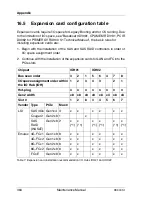
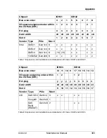
C
C
C
B
#
"
$
!
C
E
C
F
C
D
C
G
C
H
Summary of Contents for PRIMERGY RX900 S1
Page 1: ...Maintenance Manual English PRIMERGY RX900 S1 Server Maintenance Manual Edition August 2010 ...
Page 6: ...6 Maintenance Manual RX900 S1 ...
Page 52: ...52 Maintenance Manual RX900 S1 Basic procedures ...
Page 100: ...100 Maintenance Manual RX900 S1 Hard disk and solid state drives ...
Page 180: ...180 Maintenance Manual RX900 S1 Expansion cards and BBU ...
Page 198: ...198 Maintenance Manual RX900 S1 Main memory ...
Page 226: ...226 Maintenance Manual RX900 S1 Optical and backup drives ...
Page 246: ...246 Maintenance Manual RX900 S1 Front panel and external connectors ...
Page 260: ...260 Maintenance Manual RX900 S1 Management and diagnostics modules ...